19
Gas Supply Connection
The heater must be isolated from the gas supply piping
system by closing the manual shut-off valve during any
pressure testing of the gas supply piping system at test
pressures equal to or less than 1/2 psi (3.45 kPa). Re
-
lieve test pressure in the gas supply line prior to recon-
necting the heater and its manual shut-off valve to the
gas supply line.
FAILURE TO FOLLOW THIS PRO-
CEDURE MAY DAMAGE THE GAS VALVES
. Over
pressurized gas valves are not covered by warranty.
A
CAUTION:
The heater must be disconnected
from the gas supply during any pressure testing
of the gas supply system at test pressures in ex-
cess of 1/2 psi (3.45 kPa).
Fig. 14: Gas Supply Connection
A
CAUTION:
Do not use Teflon tape on gas line
pipe thread. A pipe compound rated for use with
natural and propane gases is recommended.
Apply sparingly only on male pipe ends, leaving
the two end threads bare.
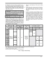
Table I: Maximum Equivalent Pipe Length
Natural gas – 1,000 BTU per ft
3
, .60 specific gravity at 0.5 in. WC pressure drop
Propane gas – 2,500 BTU per ft
3
, 1.53 specific gravity at 0.6 in. WC pressure drop
Model
No.
3/4”
1”
1-1/4”
1-1/2”
2”
2-1/2”
3”
4”
N
P
N
P
N
P
N
P
N
P
N
P
N
P
N
P
399B
15
25
60
100 260 250
499B
65
150 130 360 500
649B
45
100
95
250 340
749B
35
80
75
180 260 600
899B
20
45
45
110 150 360 400
989B
120 300 300
1259B
75
180 170 325 560
1529B
50
120 125 250 400
1799B
40
100 100 225 340
1999B
30
80
75
175 260
2069B
30
80
75
175 260
2339B
20
55
55
135 160 400 600
Gas piping must have a sediment trap ahead of the
heater gas controls, and a manual shut-off valve locat
-
ed outside the heater jacket. It is recommended that a
union be installed in the gas supply piping adjacent to
the heater for servicing. A pounds-to-inches regulator
must be installed to reduce the gas supply pressure to
a maximum of 10.5 in. WC for natural gas and 13.0 in.
WC for propane gas. The regulator should be placed
a minimum distance of 10 times the pipe diameter up-
stream of the heater gas controls. Refer to Table I for
maximum pipe lengths.
The heater and its gas connections shall be leak-tested
before placing the appliance in operation. Use soapy
water for leak test. DO NOT use an open flame.
Summary of Contents for Raypak Delta Limited 399B
Page 39: ...39 Wiring Diagram Models 399B 1259B...
Page 40: ...40 Wiring Diagram Models 1529B 2339B...
Page 51: ...51 DIAGNOSTIC DETAIL 12 J 7 J 6 J 5 J 3 0 2 0 16 S 1 F 2 F 3 F 4 F BLOWER DETAIL...
Page 53: ...53 13 J 8 J 10 J 11 J 4 J 2 J 3 J 6 C 14 J 9 J 1 J CONTROL BOX DETAILS...
Page 57: ...57 ILLUSTRATED PARTS LIST MODELS 989B 2339B 10 J 3 O 5 O...
Page 58: ...58 12 H 6 H 7 H 8 H 2 H 9 H 3 H 5 H 1 H 4 H 1 P HEAT EXCHANGER DETAILS BURNER ASSEMBLY DETAILS...
Page 59: ...59 CONTROL BOX DETAILS 9 J 8 J 23 S 13 J 10 J 3 O 10 J 3 O 5 O FRONT SWITCH DETAILS...
Page 66: ...66...
Page 67: ...67 Raypak Inc 2151 Eastman Avenue Oxnard CA 93030 805 278 5300 Litho in U S A NOTES...


