


RFD900ux Data Sheet
www.rfdesign.com.au
4
Last update 12/09/2019
2
Specifications
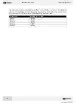
Performance
Supported RF Data Rates
12, 56, 64, 100, 125, 200, 224, 500
1
and 750kbps
1
Indoor Range
500m
–
1km
Line-Of-Sight Range
40km or more depending on antennas
Transmit Power
0 to 30dBm in 1dBm steps
Receiver Sensitivity
113dBm @ 10
-5
BER 12Kbps
1
High RF data rates are for experimental purposes only
Features
Serial Data Interface
+3.3V nominal, 3.3V tolerant
Configuration Method
AT Commands, APM Planner, Customised Configuration Tool
Frequency Band
Unlocked
902MHz - 928MHz
AU locked
915MHz - 921MHz
NZ locked
920.75MHz
–
927.25MHz
US locked
902MHz - 915MHz
Interference Immunity
FHSS (Frequency Hopping Spread Spectrum)
Serial Interface Data Rate
2400, 4800, 9600, 19200, 38400, 57600, 115200, 460kbps
Antenna Connection
2 x RPSMA diversity switched ports
GPIO
6 pins (Digital, PPM capable)
Compliance Standards
FCC Part 15.247, AS/NZS 4268:2012
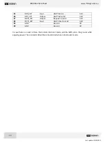
Networking and Security
Addressing Options
Network ID: 0
–
255
Channels
Unlocked
Up to 50 Frequency Hopping Channels
AU locked
23
NZ locked
25
US locked
51
Supported Network Topologies
Point-to-point, multipoint
2
, and asynchronous non-hopping
mesh
2
2
Only available in separate firmware versions available in the website
Power Requirements
Supply Voltage
+5V nominal (+5V min, +5.5V Max, +6V ABS Max),
Transmit Current
~1A peak at max power
Receive Current
~60mA


