RFD TX Module User Manual
www.rfdesign.com.au
3
Version 1.0 Last update 07/03/2019
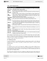
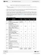
Table 1 - TX Module Description
#
Description /Note
1
Antenna
connectors
For further information about the antennas, refer to
section 5
in this document
or to the RFD 900x Modem datasheet linked in
section 7.
2
Heat sink
The heatsink, visible through the top cover is required for proper operation and
should not be covered while the unit is in use.
3
Status LEDs
Red
Blinks slowly a few times - indicates establishing link to a WiFi client.
Blinks rapidly for some time - flashing the modem firmware
Solid - device initialisation has completed
Green
Blinking
–
RFD modem looking for a link
Solid
–
RFD modem bound to another modem
4
Button
Press 5 times within 5 seconds to reset all WiFi settings to default values.
5
Tabs
To lock the TX Module into the radio control socket.
6
RC and
TX Module
Interface.
∗
a
PPM
Sends RC data into TX Module.
b
+6 V
6V supply positive terminal (not used by the module)
c
+Bat
Positive battery terminal (supply for the module)
**
d
GND
Ground
e
-
Not connected
∗
Interface between RC and TX Module is done through a female 0.1
”
pitch connector.
**
See
Table 2
below for
module supply ratings and
section 6.1
for the relation between battery voltage and
current draw with different battery types.
Table 2 - TX Module Supply Ratings
Parameter
Minimum
Maximum
Units
Supply Voltage (+Bat relative to GND)
+5
+18
V
Operating Current Draw
N/A
1.2
*
A
∗
Rating for TX Module with RFD modem set for maximum 1W transmit power measured at 5V supply.


