background image

8

RP-HRPD-IOM (07-22) 132210-B

GENERAL INFORMATION—CONTINUED

Hazards of Chlorine

NOTE:  Remember, chlorine is heavier than air. This fact should be kept in mind when determining 

the installation location of heaters and building exhaust systems.

The presence of chlorine vapors in the combustion air of heating equipment presents a potential corrosion hazard . 

Chlorine, found usually in the form of Freon or degreaser vapors, when exposed to flame will precipitate from the 

compound and form a solution with any condensation present in the heat exchanger or associated parts . The result 

is hydrochloric acid, which readily attacks all metals, including 300 grade stainless steel . Care should be taken to 

separate these vapors from the combustion process . This may be done by wise location of the unit  with regard to 

exhausters or prevailing wind directions .

INSTALLATION

NOTE:  Before installation, make preparations for necessary supplies, tools, and manpower.

Uncrating/Unpacking


This furnace was test-operated and inspected at the factory prior to crating and was in operating condition . If 

the furnace has incurred any damage in shipment, document the damage with the transporting agency and 

immediately contact an authorized Reznor

®

 distributor . If you are an authorized Distributor, follow the FOB freight 

policy procedures .


Check the rating plate for the gas specifications and electrical characteristics of the furnace to ensure that they 

are compatible with the gas and electric supplies at the installation site .

Shipped-Separate Parts


Check to see if there are any field-installed options that need to be connected to the furnace prior to installation .


Shipped-separate options could include a gas shutoff valve, a vertical vent terminal, a thermostat, an optional  

control, and disconnect switch .


Some gas control options will have parts either shipped loose with the heater or shipped separately . If the unit is 

equipped with any of the gas control options listed in 

Table 6

, ensure that these parts are available at the job site .

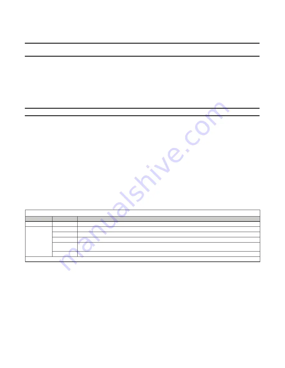
Table 6.  Shipped-Separate Parts for Gas Control Options

Application

Option

Part(s)

Heating

AG7

Thermostat (PN 48033)

Makeup air

AG3, AG4

Control switch (PN 29054)

AG8

Control switch (PN 29054); sensor and mixing tube (PN 48041)

AG9

Control switch (PN 29054); remote temperature selector (PN 48042); sensor and mixing tube (PN 48041)

AG15, AG17 Control switch (PN 29054); remote temperature selector (PN 115848); stage adder module (PN 115849); 

discharge air sensor holder (PN 115850); discharge air sensor holder bracket (PN 213612)

AG39, AG41 Remote temperature selector (PN 174849); temperature sensor (PN 133228); mixing tube (PN 90323)

NOTE: If an optional remote console is ordered, the control switch and temperature selector may be mounted on the console .

Pre-Installation Modifications

High CFM Conversion

This unit was factory assembled with the air throughput range listed on the rating plate . If the application requires 

a higher CFM than listed on the rating plate, the unit may be converted for lower temperature rise and higher CFM . 

The conversion will change the air throughput range as specified in 

Table 7

 . Verify the unit size on the heater rating 

plate and, after confirming that this conversion is correct for the unit, perform the following procedure:

Summary of Contents for HRPD

Page 1: ...agency or the gas supplier Be sure to read and understand the installation operation and service instructions in this manual Do not store or use gasoline or other flammable vapors and liquids in the...

Page 2: ...Piping Connections 19 Electrical Connections 21 Control Wiring 21 CONTROLS 22 Thermostat 22 Fan Control 22 Limit Control 22 Combination Gas Valve 22 Combustion Air Proving Switch 23 Optional Two Stag...

Page 3: ...g rate and electrical requirements are shown on the unit s rating plate Model HRPD is dual model RP furnaces configured for higher CFM capacity References TABLE OF CONTENTS CONTINUED OPERATION 29 Pre...

Page 4: ...thoroughly before installing or servicing this equipment WARNING For your safety read the warning labels on the unit CAUTION These duct furnaces are not certified or approved for use in drying or proc...

Page 5: ...spark ignition flame sensing probe b Wiring is not in accordance with the diagram furnished with the heater c Unit is installed without proper clearance to combustible materials or without proper ven...

Page 6: ...Figure 1 Unit Size 125 150 175 200 225 250 300 350 400 Inches 1 8 mm 3 A 30 15 16 786 36 7 16 914 41 15 16 1065 50 3 16 1275 55 11 16 1414 61 3 16 1554 B 28 1 2 648 34 864 39 1 2 1003 47 3 4 1213 53 1...

Page 7: ...provided Table 4 Weights Model RP Unit Size 125 150 175 200 225 250 300 350 400 HRPD Unit Size 250 300 350 400 500 600 700 800 Pounds kg RP 201 91 217 98 247 112 295 134 333 151 361 164 HRPD 402 182 4...

Page 8: ...s Check to see if there are any field installed options that need to be connected to the furnace prior to installation Shipped separate options could include a gas shutoff valve a vertical vent termin...

Page 9: ...cy performing this work assumes responsibility for the conversion of this appliance to provide for higher CFM Theseinstructionsaredesignedtopreparetheductfurnaceforincreasedairthroughputconversion pri...

Page 10: ...ffle b Remove both side finger baffles Figure 4 Side Finger Baffle Removal 3 Install field conversion label see Figure 5 a Fill in field conversion label PN 263310 from literature bag b Adhere label t...

Page 11: ...ket assembly on opposite end of heat exchanger and secure using field supplied sheet metal screws 4 Reinstall airflow baffles removed in step 1 and secure using existing screws Figure 6 Airflow Baffle...

Page 12: ...1 inch is recommended of insulation Supports suspend all ducts securely from buildings members Do not support ducts from unit duct connections Access panels Install removable access panels see Figure...

Page 13: ...ischarge sensor is field supplied Follow the instructions below to install the sensor in the ductwork 1 Determine distance of sensor from unit a Ensure that there is sufficient distance from outlet to...

Page 14: ...nse air temperature as it flows through holes in holder 3 At selected ductwork location mark diamond shaped hole approximately 1 1 inch 25 25 mm required for sensor holder or round hole required for m...

Page 15: ...40 3070 0 28 2630 0 23 2300 0 22 2045 0 21 300 4420 0 58 3685 0 39 3160 0 29 2765 0 25 2455 0 22 350 5160 0 65 4300 0 44 3685 0 31 3225 0 25 2865 0 23 400 5895 0 70 4915 0 50 4210 0 30 3685 0 30 3275...

Page 16: ...Duct Furnace Blower Connections Bypass Duct Construction When the air throughput CFM is greater than desirable or permissible for the unit a bypass duct see Figure 11 may be constructed Locate the byp...

Page 17: ...110 3290 9 229 1700 2100 2400 2700 2970 3200 3400 3600 3800 10 254 1920 2350 2760 3090 3650 4020 4300 4550 4800 See Figure 11 NOTE Not all capacities are covered above If your installation is not cove...

Page 18: ...ater Gas Supply Piping DANGER All components of a gas supply system must be leak tested prior to placing equipment in service NEVER TEST FOR LEAKS WITH AN OPEN FLAME Failure to comply could result in...

Page 19: ...ne Gas Natural Gas Propane Gas Cubic Feet per Hour 20 92 56 190 116 350 214 730 445 1100 671 2100 1281 30 73 45 152 93 285 174 590 360 890 543 1650 1007 40 63 38 130 79 245 149 500 305 760 464 1450 88...

Page 20: ...ued Figure 13 Gas Connections Table 13 Gas Connection Sizes Gas Type RP Unit Size 125 250 300 400 HRPD Unit Size 250 500 600 800 Connection Size Inches mm Natural gas 1 2 13 3 4 19 Propane 1 2 13 NOTE...

Page 21: ...y with fused disconnect switch should be run directly from the main electrical panel to the unit making connections in the junction box Disconnect switch A disconnect switch is a required part of this...

Page 22: ...t Use either an optional thermostat available with the system or a field supplied thermostat Install according to the thermostat manufacturer s instructions Fan Control NOTE To replace the fan control...

Page 23: ...odels HRPD Models Units Without Option AG39 AG40 AG41 or AG42 All 0 58 0 05 IN WC 1 05 IN WC 0 73 IN WC Units with Option AG39 AG40 AG41 or AG42 125 225 250 400 0 58 0 05 IN WC 1 30 0 20 IN WC 1 05 0...

Page 24: ...es 64 F low stage furnace 2 68 F shutdown furnace 2 70 F low stage furnace 1 74 F shutdown furnace 1 AG4 HRPD 2 70 F 66 F full rate both furnaces 70 F shutdown furnace 1 74 F shutdown furnace 2 AG15 R...

Page 25: ...n the heater rating plate AG7 is identified as MV 1 AG8 is identified as MV 3 AG9 is identified as MV 4 AG21 is identified as MV A AG39 is identified as MP 1 and AG40 is identified as MP 2 AG39 and AG...

Page 26: ...ual to or greater than the thermal efficiency at full fire The gas train see Figure 16 includes a single stage gas valve a modulating valve and two gas pressure switches The burner rack is equipped wi...

Page 27: ...gear motor Replace primary manifold pressure switch YES NO YES NO YES NO YES NO YES NO NO YES YES NO Measure manifold pressure during burner cycling When the manifold pressure is BELOW 1 0 w c is the...

Page 28: ...is available only with model HRPD natural gas units and is not available on unit size 700 Depending on its size a furnace equipped with option AG40 or AG42 has a 20 28 turndown ratio With option AG40...

Page 29: ...trolled flame stability without lifting or flashback with either natural or propane gas All burners are lightweight and are factory mounted in an assembly that permits all of the burners to be removed...

Page 30: ...The result is incomplete combustion which produces carbon monoxide a poisonous gas that can cause death Safe operation of indirect fired gas burning equipment requires a properly operating vent syste...

Page 31: ...when the heater is in operation and when it is on standby Incorrect inlet pressure could cause excessive manifold gas pressure immediately or at some future time NOTE A manometer fluid filled gauge i...

Page 32: ...turn using wrench DANGER DO NOT use an open flame to check for gas leaks Table 20 High Elevation Burner Orifices Installation Elevation Feet Meters Installation Location RP Unit Size Natural Gas Propa...

Page 33: ...rclockwise to close the air shutter After the furnace has been in operation for 15 minutes close the air shutter until the flame turns yellow Open the shutter until yellow disappears Adjust Heat Stage...

Page 34: ...ion and clean as necessary Clean all dirt and grease from primary and secondary combustion air openings Power vent Check flue products outlet and clean as necessary Gravity vent Check vent cap or opti...

Page 35: ...connect electric valve leads e Uncouple union in gas supply f Remove sheet metal screws in top corners of burner rack assembly g Pull drawer type burner rack out of furnace 2 Disassemble burner rack N...

Page 36: ...l sensing probe and the pilot hood with an emery cloth and wipe off the ceramic insulator 4 Check the spark gap see Figure 20 which should be maintained to 7 64 inch Figure 20 Pilot Assembly Spark Gap...

Page 37: ...a If voltage between black and brown leads on main gas valve is 20 32 VAC and there is no main gas flow with built in manual valve in FULL OPEN position main valve is defective b If there is no voltag...

Page 38: ...ner Rack Maintenance section b Remove heat exchanger V baffles see Figure 22 1 Remove ends of flue gas collection box 2 On control side of furnace remove venter assembly and flue outlet duct to gain a...

Page 39: ...l lockout device interrupting control circuit due to above causes Reset lockout by interrupting control at thermostat 9 Faulty combustion air proving switch Replace combustion air proving switch C Pil...

Page 40: ...__________ Address ________________________________________________________ ________________________________________________________ Phone ________________________________________________________ Mode...

Reviews: