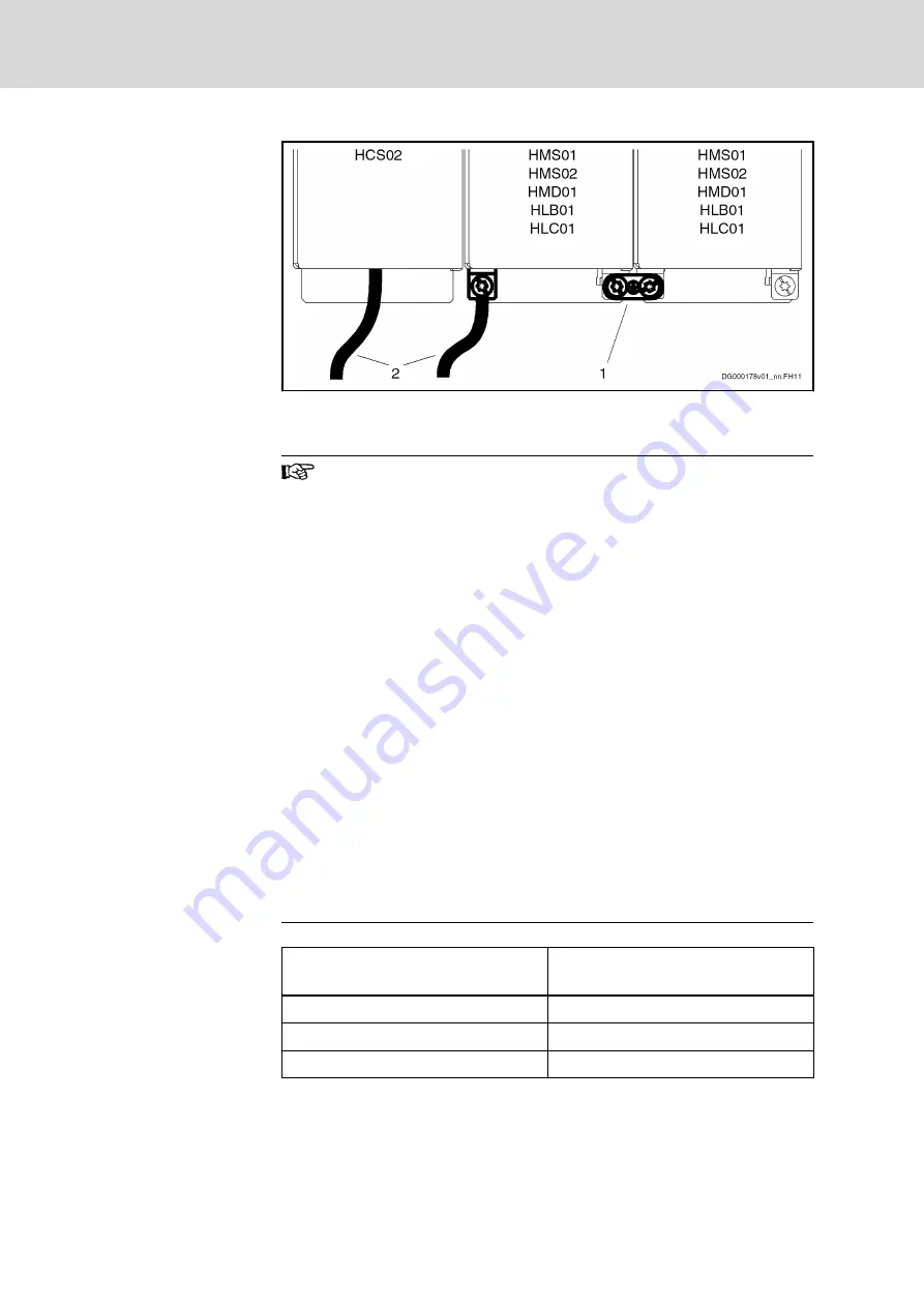
1
Joint bar
2
Connection to equipment grounding system
Fig.13-5:
Equipment Grounding Conductor Connection for Supply via HCS02
Equipment grounding conductor: Material and cross section
For the equipment grounding conductor, use the same metal (e.g.
copper) as for the outer conductors.
For the connections from the equipment grounding conductor
connection of the device to the equipment grounding conductor
system in the control cabinet, make sure the cross sections of the
lines are sufficient.
Cross sections of the equipment grounding connections:
●
For HCS03.1E drive controllers, HMV01 and HMV02 supply
units at least 10 mm
2
(AWG 8), but not smaller than the
cross sections of the outer conductors of the mains supply
feeder
●
For HCS02.1E drive controllers, at least 4 mm
2
(AWG 10),
but not smaller than the cross sections of the outer conduc‐
tors of the mains supply feeder
Additionally, mount the housing of HCS02.1E to a bare met‐
al mounting plate. Connect the mounting plate, too, with at
least the same cross section to the equipment grounding
conductor system in the control cabinet.
For outer conductors with a cross section greater than 16 mm²,
you can reduce the cross section of the equipment grounding
connection according to the table "Equipment Grounding Conduc‐
tor Cross Section".
Cross-sectional area A of outer conduc‐
tors
Minimum cross-sectional area A
PE
of
equipment grounding connection
A ≤ 16 mm²
A
16 mm² < A ≤ 35 mm²
16
35 mm² < A
A / 2
Tab.13-2:
Equipment Grounding Conductor Cross Section
13.1.5
Connection to Mains Choke and Mains Filter
Order of the connections to the supply mains:
Bosch Rexroth AG
DOK-INDRV*-SYSTEM*****-PR06-EN-P
Rexroth IndraDrive Drive Systems with HMV01/02 HMS01/02, HMD01, HCS02/03
226/309
Connections of the Components in the Drive System


