Falk
®
Rigid Moment Couplings
•
Installation & Maintenance
Type MCF
•
Size 1135
(Page 3 of 4)
Rexnord
CP3-006
5555 S. Moorland Rd., New Berlin, WI 53151-7953
February 2015
Telephone: 262-796-4060 Fax: 262-796-4064 www.rexnord.com
NEW
Coupling Disconnection
WARNING
:
Do not disconnect torque arm or tie rod until
the low-speed coupling is completely disconnected.
1. With suitable equipment, remove the weight of the
drive assembly from the coupling and driven shafts. It
is necessary to make fine adjustments of position at
each of the bedplate lugs. The lifting slings should have
appropriate provisions for adjustment.
2. Lift the drive by the lifting lugs in the bedplate or wrap
slings around the assembly when a bedplate is not
used. Balance loads so drive is level and will not swing
down when the coupling is disconnected.
3. Loosen flange fasteners in sequence until all fasteners
have at least a 0.125” (3.175 mm) clearance under
the fastener heads. Remove all but one fastener near
the top of the flange. Separate the two flanges using
four 1/2–13UNC fasteners (not supplied with coupling)
inserted in the four jackscrew holes in the male register
flange. Continue backing off the last flange fastener as
the flanges are separated. When completely separated,
adjust the weight of the drive assembly until the weight
is off the last fastener. Carefully remove the last fastener.
4. Adjust the drive assembly position until all the weight of
the assembly is balanced. When the tie rod is no longer
bearing any of the weight, disconnect the tie rod. Slowly
lower the assembly to the ground.
Hub Removal
1. Type 2 Hubs
a. Thoroughly clean hubs of grease and solvents to
avoid combustion when heat is applied.
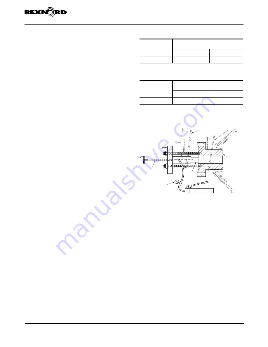
b. Assemble puller as shown in Figure 6. Check to
make sure puller has enough stroke to pull the hub
off. Be sure to adequately support both the hub and
puller assembly using metal cable slings. Reference
Table 3 for the hub puller bolt hole mounting pattern.
c. Heat the hub evenly with a rosebud torch to
approximately 400° to 500°F (204° to 260°C) while
applying pressure to the puller. The temperature may
be measured with a heat-sensitive crayon. Apply
puller pressure until the hub clears the shaft.
2. Type 6 Hubs
a. Mount a hydraulic hub puller (see Figure 7) on the
end of the hub with a pressure rod against the shaft
end. Reference Table 3 for the hub puller bolt hole
mounting pattern. The puller must have an axial
travel equal to or greater than the hub-to-shaft bore
length. Be sure to adequately support both the hub
and puller assembly using metal cable slings.
b. Mount the hydraulic expansion fittings to the hub
and high-pressure hydraulic pump. Pressurize the
hub-to-shaft interface until oil is oozing out between
bore and shaft, or to the removal pressure called
out in Table 4. Apply axial removal force at the same
time as pressurizing the hub. Shut off pressure (item
8 of Figure 7) prior to the groove being exposed
beyond the shaft end.
Table 4 — Type 6 Hub Removal Pressure
COUPLING
SIZE
Maximum Recommended Pressure At Hub Bore
When Dismounting Hub
(MPa)
(psi)
1135 MCF
138 - 152
20,000 - 22,000
Table 3 — Type 2 & Type 6 Hub Puller Bolt
COUPLING
SIZE
Flange Face Puller Bolt Holes
UNC Tap (2 x Dia Deep)
BC - Inch (mm)
UNC Tap (4 @ 180°)
1135 MCF
25.00 (635)
2.000 - 4.5UNC
METAL CABLE SLINGS
TO SUPPORT HUB
AND PULLER
TORCH
COUPLING
HUB
TORCH
SHAFT
BAR
STOCK
HAND PUMP OR
HYDRAULIC PUMP
GAUGE
WITH OR
WITHOUT
ADJUSTING
SCREW
ALLOR STEEL
PLATE
HYDRAULIC
CYLINDER
Figure 6 — BASIC TYPE 2 HUB REMOVAL EQUIPMENT


