Installation & Maintenance
•
Falk Rigid Moment Couplings
(Page 2 of 4)
Type MCF
•
Size 1135
CP3-006
Rexnord
February 2015
5555 S. Moorland Rd., New Berlin, WI 53151-7953
NEW
Telephone: 262-796-4060 Fax: 262-796-4064 www.rexnord.com
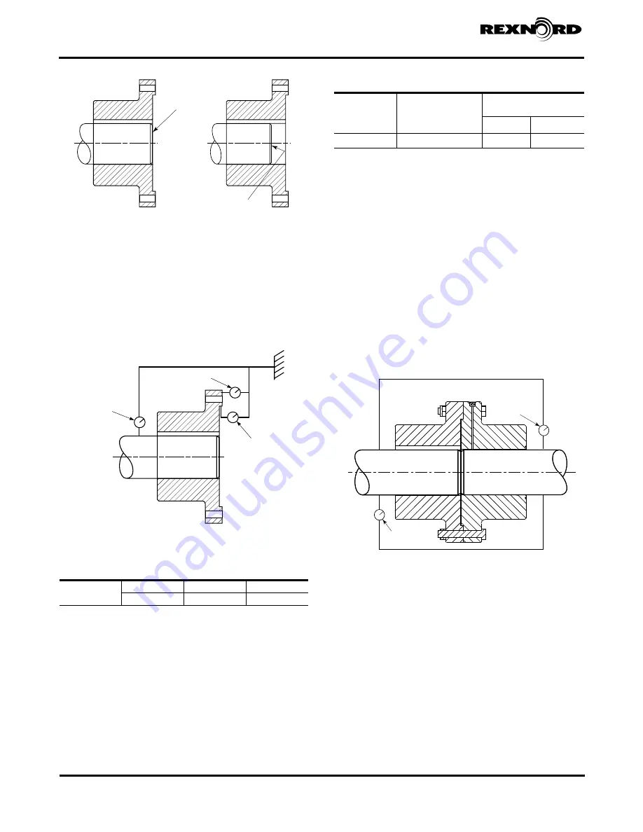
SHAFT END
FLUSH WITH
FACE OF HUB
SHAFT NOT FLUSH
WITH END OF HUB
CORRECT
INCORRECT
c. Check that the hub is correctly positioned on the
shaft, then using dial indicators, check hub runout
as illustrated in Figure 4. Checking the hub runout
ensures correctness of hub mounting and will reduce
drive movement. Make sure runout values do not
exceed limits listed in Table 1. If runout is excessive,
remove hub following the removal instructions, and
carefuly remount the hub to the shaft.
INDICATOR #3
INDICATOR #2
INDICATOR #1
Figure 3
Figure 4
7. With suitable lifting equipment, move the drive/motor
assembly into position, approximately parallel and in
line with the driven shaft using hub flanges as a guide.
Align fastener holes, and install and hand tighten one
flange fastener. Align hub registers and flange fastener
holes. Install all flange bolts finger tight.
8. Use a precision torque wrench and equally tighten all
opposing fasteners while allowing the drive assembly to
move as required to draw the flanges together (flexible
support). Continue tightening until flanges are mated
and all flange fasteners are torqued to values specified
in Table 2.
Table 2 — Flange Fastener Tightening
COUPLING
SIZE
Flange Fastener Size
Grade 8
(Inch)
Flange Fastener Tightening
Torque Tolerance 5%
(Nm)
(lb-ft)
1135 MCF
2.500 - 4 UNC x 11.00
12745
9400
9. Fasten the torque arm to the bed frame per gear drive
instructions and remove the lifting equipment. Rexnord
recommends that a loose, unrestraining safety sling
be attached to the bedplate and support structure to
support the drive in case of an emergency.
10. Using dial indicators per Figure 5, measure assembly
runout on driving and driven shafts. Runout values
should be within 0.005” (0.127 mm) TIR (total indicator
reading) to minimize drive movement. See Table 1.
11. Run the drive for a short period of time, and then
shut off and lockout motor. Recheck all fasteners for
specified torque.
12. The coupling installation is now complete.
WARNING
: Install the warning nameplate supplied
with the coupling on the coupling guard or on some
other support structure near the coupling.
DIAL
INDICATOR
DIAL
INDICATOR
REVERSE DIAL INDICATOR METHOD
Figure 5
Table 1 — Maximum Runouts (TIR) for Dial
Indicators – Inch (mm)
All
Sizes
#1
#2
#3
.001 (0.025)
.003 (0.076)
.003 (0.076)


