background image


37 

Pairing 

All FLX2 wireless components are paired before the system is shipped, providing much 
of the system setup already completed. While pairing should not be required for the 
system to work, sometimes components can require pairing if a part is shipped 
separately. The following aree instructions on how to pair the wireless components of 
the system to the FLX2 Conference Phone. 

To pair the FLX Dialer, follow this procedure.  Please note that Microphones and 
Speakers require a Dialer to be paired with the Base Station before you can pair them. 

Dialer 

1.


If the Dialer is turned on, turn it 

off by pressing and holding the red ‘end call’ 

button until an overlay appears asking whether you want to shut the Dialer down. 
Press ‘Yes’. 

2.


Plug in the FLX2 Base Station.  

3.


Turn the Dialer 

back on (press the red ‘end call’ key).  The screen should read 

“Scanning for new base”.  If the screen reads “scanning for paired base”, press 
the ‘Stop’ button, press the ‘Menu’, and select ‘Re-Pair’.  When asked whether to 
‘Scan for New Base’, select ‘Yes’. 

4.


After some time scanning for available bases, an overlay will appear a

sking ‘Pair 

with <System Name>?’  Select ‘Yes’. 

5.


An overlay, ’Pairing with base <System Name>’, should appear followed by a 
‘Connecting…’ and then and ‘Initializing…’ screen. Shortly after that the Dialer 
home screen will appear.  Your Dialer is now paired.  

6.


If the Dialer does not automatically pair, repeat steps 1-5.  If this still does not 
resolve the problem, select “Reset Factory Defaults” as this will force a scan for a 
new base. 

Speaker 

1.


To pair a Speaker, if the Speaker is turned on, turn it off 
by pressing and holding the button on the bottom of the 
Speaker until you hear the Speaker shut-off or the 
LEDs turn off. 

2.


Ensure that the Base Station is plugged in and powered 
up. 

3.


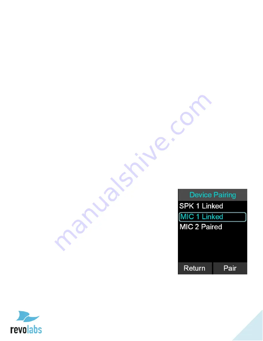
On the Dialer, browse to the Pairing menu: Menu 


Setup 

 Advanced Setup 

 Pairing. 

4.


Select SPK 1 (Speaker 1) and press the 

‘Enter’ or ‘Pair’ 

key to enter pairing state. 

5.


The screen 

will display ‘Pairing Speaker 1’. 

6.


Press and hold the button on the bottom of the Speaker 
until the LED turns solid red. 

7.


An overlay will appear on the Dialer 

“Pairing 

Successful”, after that the screen should read ‘SPK 1 
Linked

’. 

8.


If pairing was unsuccessful, the Speaker will show an 
alternating red -green slow blinking sequence indicating 


Summary of Contents for FLX2 10-FLX2-002-POTS

Page 1: ...REVOLABS FLX2TM Wireless Conference System for analog phone lines System Guide Models 10 FLX2 200 POTS 10 FLX2 020 POTS 10 FLX2 002 POTS 10 FLX2 101 POTS...

Page 2: ...of this document may be reproduced in any form or by any means without express written permission from Revolabs Inc Product specifications are subject to change without notice Revolabs FLX2 System Gu...

Page 3: ...he FLX2 components to water moisture or high humidity Do not expose any of the FL2X components to extreme high or low temperatures Do not expose any of the FLX2 components to lit candles cigarettes ci...

Page 4: ...ll 17 Ignoring an Incoming Telephone Call 18 Ending a Telephone call 18 Calling a Directory Contact 18 Active Call Management 19 Charging Components during a Call 21 Bluetooth 21 Activating Bluetooth...

Page 5: ...paired with Base Station 41 LED Indicators 42 Reset to Factory Defaults 43 Technical Specifications 44 Models 44 Regulatory Information 46 FCC Notice to Users 46 Industry Canada Notice to Users 46 Re...

Page 6: ...the Charge Base Speaker Microphones and Dialer handset In addition the Base Station receives the wireless signals from those components and connects into your telephone network for conference calls w...

Page 7: ...le Use the 5 Volt power supply to connect the Base Station to mains power The Base Station will power up Connecting the Charger Base Place the Charger Base at a location where you can easily access th...

Page 8: ...ing to dial the number At this point only the Dialer will be used for the call To end the call press the red hang up button on the Dialer With a Microphone out of the Charger Tray you can toggle betwe...

Page 9: ...less LANs 802 11b g without interference The Revolabs FLX2 Conference Phone includes digital encryption technology to ensure secure wireless communications between the Microphones Speaker and the Base...

Page 10: ...wirelessly The Base Station is designed to optimize audio and video conferencing by providing consistent audio input from all participants The FLX2 Base Station is shown in rear panel view below It i...

Page 11: ...simple and organized location The FLX2 Charger Base is not required while in a conference call however it can maintain the charge of the FLX Speaker and FLX Dialer while a call is in progress Micropho...

Page 12: ...Dialer is not only used to make and answer conference calls but it is also used for configuring the system settings answering a call using the handset and monitoring the system components The FLX Dial...

Page 13: ...and optimized specifically for use with the FLX Conferencing System The Speaker is equipped with a pairing button on the bottom and 4 LED indicators on the top to display the activity of the Speaker a...

Page 14: ...if the Microphones have lost connection to the Base Station The FLX Microphones shown below come in three different versions to provide a flexible solution to meet all applications of conferencing sp...

Page 15: ...he FLX2 Wireless Conferencing system is equipped with a telephone interface that allows the system to make telephone conference calls The following are the basic operational instructions for making an...

Page 16: ...be made at the same time as a video call Telephone calls are controlled via the FLX Dialer Bluetooth Call The FLX2 System is equipped with a Bluetooth interface that allows a call to be made through...

Page 17: ...ialer is not in the Charger Base it will also play a ring tone 2 If your phone line supports caller ID and the caller has not suppressed their caller ID information the FLX Dialer will display the cal...

Page 18: ...X Dialer during a call b Place the Dialer in the charger handset mode Only c Place all the Microphones in the charger speaker mode Only 2 When a call is ended the FLX Dialer will display the phone num...

Page 19: ...ncoming information from the network which might include the telephone number and Caller ID Note An incoming Bluetooth call will display caller ID information as well Muting a Call 1 In handset mode t...

Page 20: ...ialer will play the call waiting indication tone 2 If available the FLX Dialer displays the incoming caller number and name 3 The FLX Dialer presents the user with the option to Answer the call 4 If n...

Page 21: ...ute until the reboot is complete Approximately 6 seconds Once the Speaker reconnects the audio will resume When the Speaker is removed from the charger no change to call activity will take place Micro...

Page 22: ...vices 2 The FLX Dialer displays This device is visible to other devices in range for 3 minutes 3 Scan for devices from the Bluetooth device you want to connect to the FLX2 System 4 When the FLX2 Syste...

Page 23: ...into range with the FLX2 System a message will appear on the FLX Dialer 1 Select Yes to have the FLX2 System pair with the Bluetooth device and be ready for use 2 Select No to have the FLX2 System ig...

Page 24: ...m This allows the FLX Microphones and Speaker to be used as Microphones and Speaker for the video call It also provides Acoustic Echo Cancelation and Noise Control to the video call Connecting a Video...

Page 25: ...ion 2 Up and Down navigation keys are used to scroll through the menu The Left navigation key will return to the previous menu 3 When setting levels such as Volume in the menus the Up and Down keys ar...

Page 26: ...ed directly from the home screen by pressing green Call button in idle state 5 The recent call log is limited to 20 entries Call Recent Caller 1 Access the recent call log by browsing Menu Recent Call...

Page 27: ...in progress 2 In the recent call list select the entry you want to add to the contacts and press View This displays more information for the recent call you selected 3 Press the Save key to save the...

Page 28: ...ion or select Delete All Calls to delete all call history information 4 Press Yes to delete the information when prompted for confirmation Contacts The FLX Dialer can store 99 entries in a contact dir...

Page 29: ...ss the contact 2 The contact screen shows the current name and number Pressing the Edit key will open the Edit Contact menu 3 In the Edit Contact menu select Edit Info to edit the selected contact 4 E...

Page 30: ...tered any contact name starting with C will be shown The user can scroll through the filtered list using the up and down buttons View Contact Information 1 Browse to the Contacts menu Menu Contacts 2...

Page 31: ...Speed Dial X Audio Control The following is a list of FLX Dialer menus that adjust the system attributes related to speaker audio Analog audio inputs outputs and telephony audio configurations Speaker...

Page 32: ...s enter to set the selected ring tone Equalizer EQ 1 Browse to the Equalizer Settings menu Menu Audio Controls EQ 2 Use the up and down buttons to select a preset EQ and press enter to set the selecte...

Page 33: ...tion 3 Device Versions shows firmware version for the Speaker SPK and Microphones MIC1 MIC2 4 System Versions shows the firmware versions for the Application APP Baseband BB Bluetooth Dialer BTH and B...

Page 34: ...r Enter or Select to open that setting 4 Use the up and down buttons to increase or decrease the respective values Date Time 1 Browse to the Date Time menu Menu Setup Set Date Time 2 To set the date o...

Page 35: ...the Microphones The factory default is OFF 4 The Start Unmute feature allows the Microphones to come out unmuted when taken out of charger The factory default is ON 5 Aux Audio is to control the AUX...

Page 36: ...this Set Password 1 Browse to the Set Password menu Menu Setup Advanced Setup Admin Settings Set Password 2 Set the password to an admin specified password Note that setting this password will overrid...

Page 37: ...ime scanning for available bases an overlay will appear asking Pair with System Name Select Yes 5 An overlay Pairing with base System Name should appear followed by a Connecting and then and Initializ...

Page 38: ...as unsuccessful the Microphone will show an alternating red green slow blink sequence indicating that the pairing failed The Dialer will display a Pairing Timeout message In that case the pairing proc...

Page 39: ...lid red release the button and the Speaker will power off To power the Speaker back on either 1 Hold down the button on the bottom of the Speaker until the LED indicators on the top of the Speaker tur...

Page 40: ...aler Low Battery When the Dialer experiences a low battery it will display a low battery notification on the screen The Dialer should be returned to the charger until the battery status on the home sc...

Page 41: ...on the Microphones the Dialer and the Speaker Now power up the Base Station Once the Base Station is powered up double green flashes of the Status LED power up the Dialer and then the Microphones and...

Page 42: ...stablish the link for about 5 minutes then power off Alternating slow Red Green flash Microphone is not paired to a Base Station The microphone will power off after two minutes Steady Red o Microphone...

Page 43: ...ted battery low Master Mute or All Mic Mute is ON all microphones muted Flashing Yellow Red Yellow Green Searching for a connection to the base The speaker will try to re establish the link for about...

Page 44: ...Class II 33 feet 10 meters Security DECT Bluetooth DECT 128 bit encryption Noise Cancelation Noise cancellation on the Microphone Echo Cancelation Acoustic echo canceller for Speaker Microphone Line e...

Page 45: ...ns Telephone RJ11 USB 2 Mini USB connectors Analog IN OUT AUX OUT Line level input 2 outputs line level or mic level Indicators LED 1 indicating system status Charger Base Power 15V 1A Dimensions Char...

Page 46: ...es with FCC radiation exposure limits for an uncontrolled environment Industry Canada Notice to Users Operation is subject to the following two conditions 1 This device may not cause interference and...

Page 47: ...use of wireless devices and their accessories may be prohibited or restricted in certain areas Always obey the laws and regulations on the use of these products North American UPCS Usage Restriction...

Page 48: ...c compatibility and Radio spectrum Matters ERM Wideband transmission systems Data transmission equipment operating in the 2 4 GHz ISM band and using wide band modulation techniques Harmonized EN cover...

Page 49: ...tinuance of service may be required But if advance notice isn t practical the telephone company will notify the customer as soon as possible Also you will be advised of your right to file a complaint...

Page 50: ...intenance instructions Product modification or alteration Use of common carrier communication services accessed through the product Abuse misuse negligent acts or omissions of Customer and persons und...

Page 51: ...is warranty gives you specific legal rights which may very depending on local law Governing Laws This Limited Warranty and Limitation of Liability shall be governed by the laws of the State of Massach...

Reviews: