background image

1

 - 

2

 - 

3

 - 


4

 - 

5

 - 

6

 - 


STEP 5: PEDALS

Right Pedal

Locate the pedal stamped “

R

” on the end of the spindle (this is the 

RIGHT

 pedal) 

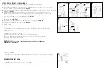
(Fig. 12)

.

RECOMMENDED

; Apply a thin layer of grease to the pedal threads prior to installation.

Carefully insert the Right pedal into the Right side crank arm (the side with the chain) and thread it 

Clockwise


(Fig. 13)

. You should be able to thread the pedal in part of the way by hand with minor 

resistance. If it seems difficult and binds, stop, remove the pedal, realign the threads and try again. Be sure you are turning the right pedal axle in a clockwise direction!
Tighten the pedal with a 15mm or adjustable wrench until the pedal is securely attached to the crank arm. The pedals need to be tightened with a considerable amount of force so that they do not come 
loo se.

Left Pedal

Locate the pedal stamped “

L

” on the end of the spindle (this is the 

LEFT

 pedal) 

(Fig. 12)

.

RECOMMENDED; apply a thin layer of grease to the pedal threads and insert your Left pedal into the Left side crank arm.
Thread it 

Counterclockwise

 and tighten with a 15mm or adjustable wrench following the instructions in step #3 above 

(Figure 14).

NOTE: Be sure to tighten both pedals with an adjustable wrench or 15mm open end wrench to the recommended torque specification 

otherwise they will unscrew while riding causing an unsafe condition for the rider and damaging the threads in the crank.

12

13

right pedal

clockwise

tighten

14

left pedal

counter clockwise

tightn

Summary of Contents for KODA 12

Page 1: ...he quick release lever attached to the top of the frame seat tube outwards Insert the seat post saddle assembly into the seat tube of the frame to at least the minimum insertion line of the seat post Fig 2 Adjust the seat to your desired height Once you have adjusted the seat post to your desired height lock it in place by closing the quick release lever against the clamp Fig 3 The lever should re...

Page 2: ...ter forward direction from the factory If adjustment is needed use the following steps 1 2 3 You may have to loosen or remove one brake pad pad to fit the wheel in the front fork Fig 10 When tightening or reinstalling make sure the brake pad is aligned with the curve of the rim and the pad contacts the rim surface flat and evenly 4 STEP 4 FRONT WHEEL 8 Remove the plastic shipping protector from th...

Page 3: ...ench until the pedal is securely attached to the crank arm The pedals need to be tightened with a considerable amount of force so that they do not come loo se Left Pedal Locate the pedal stamped L on the end of the spindle this is the LEFT pedal Fig 12 RECOMMENDED apply a thin layer of grease to the pedal threads and insert your Left pedal into the Left side crank arm Thread it Counterclockwise an...

Page 4: ...g 16 Squeeze the brake lever firmly several times to take the stretch out of the cable and make sure that it does not slip through its anchor If the cable tension is too tight to allow the wheel to spin freely loosen the anchor bolt and give the cable some slack If the cable has too much slack and you cannot apply enough stopping force to the rim repeat procedure 3 to take the slack out of the cab...

Page 5: ...or floor pump with a gauge begin to inflate the tire to half its recommended inflation pressure and check to see that the tire is properly seated on the rim Be sure to inspect both sides of the tire for proper fit If the tire is seated unevenly or bulges out along the rim let some air out of the tire and reposition the tire by hand so that it sits evenly on the rim Continue to inflate the tire to ...

Reviews: