Response SA5 E Installation And Operating Instructions Manual Download Page 15

6.

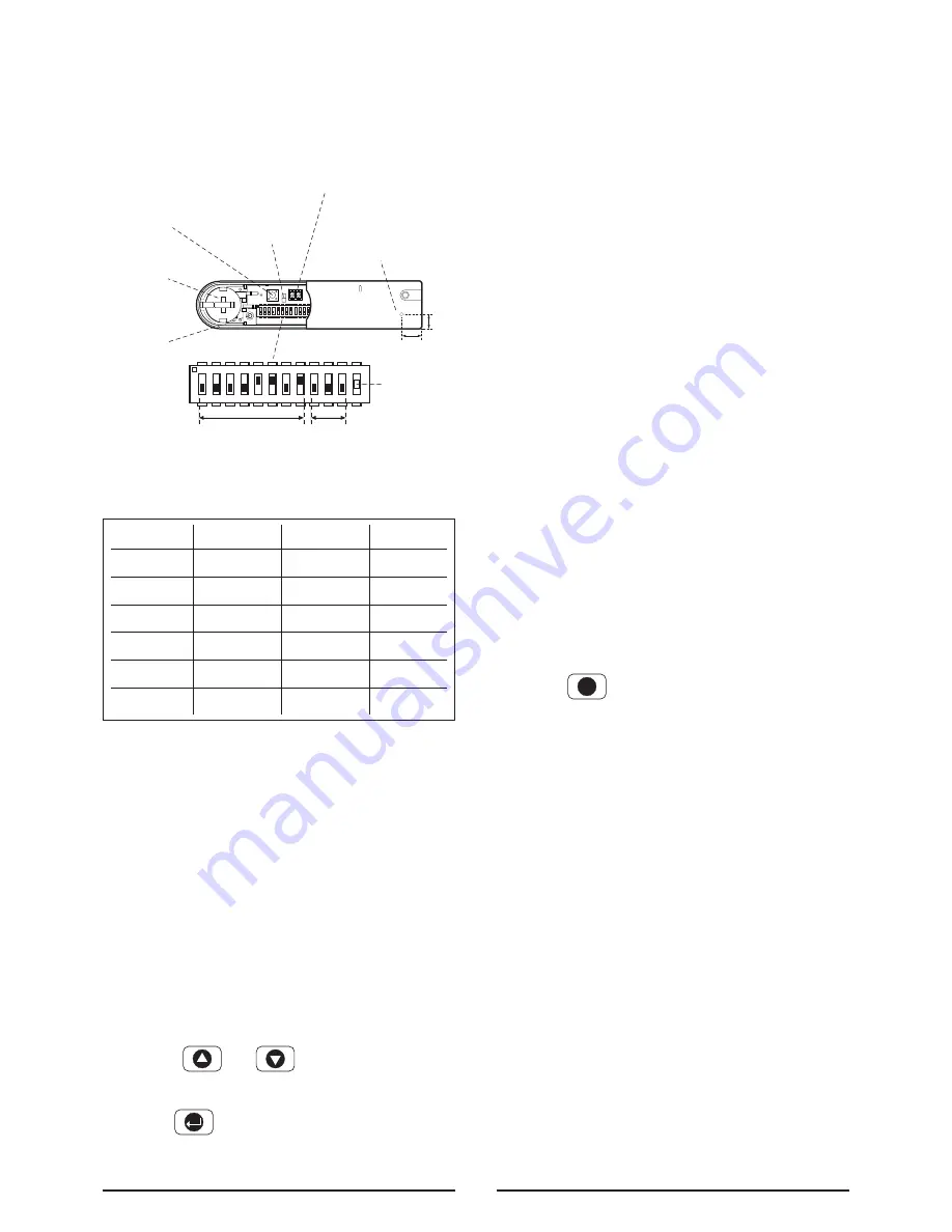
Set  the  House  Code  for  the  Magnetic  Contact

Detector  by  setting  DIP  switches  1-8  to  the  same

ON / OFF  combination  as  the  House  Code  DIP

switches in all other system devices.

7.

Set the alarm zone which the Detector will operate

on with DIP switches 9-11 as follows:

8.

Slide  the  two  batteries  supplied  into  the  battery

holder,  ensuring  that  the  positive  (+)  side  is

uppermost on each battery as it is installed.

9.

Carefully refit the battery holder onto the Detector

ensuring  that  the  spring  connectors  slide  onto

either side of the circuit board.

10. Fit the battery cover into position on the Magnetic

Contact Detector.

Testing the Magnetic Contact
Detectors

Ensure that the Contro Panel is in Test mode.

1.

Use the              and              buttons to scroll through

the menu until 

‘WALK TEST’ 

is displayed.

Press            to activate Walk Test.

‘ Walk Test Waiting…’ 

will be displayed. 

2.

Remove the battery cover by sliding off..

As  the  battery  cover  is  removed  the  LED  on  the

Detector  will  illuminate  for  approx.  1  second  to

indicate  that  the  tamper  switch  has  been

activated.  In addition, the Control Panel will beep

to indicate that an alarm signal has been received

and ‘Accessory Tamper’ will be displayed.

3.

Open  the  door/window  to  detach  the  magnet

from the Detector.  As the magnet is parted from

the  detector  the  LED  will  illuminate  for  approx. 

1 second to  indicate  that  the  Detector  has  been

triggered.  In addition, the Control panel will beep

to  indicate  that  an  alarm  signal  has  been

received  and  the  identity  of  the  zone  that  the

detector is set for will be displayed.

Note:

In  normal  mode  with  the  battery  cover

fitted,  the  LED  on  the  detector  will  not  illuminate

when the detector is triggered, (unless the battery

is low).

4.

If  connected,  operate  the  wired  Magnetic

Contact.    As  the  contact  is  opened  the  LED  on

the  Detector  should  illuminate  for  1  second  to

indicate  that  it  has  been  triggered  and  the

Control Panel will acknowledge the alarm signal.

5.

Refit the battery cover on the Detector.

6.

Press                to  return  to  the  top  level  menu  of

Test Mode.

External Solar Siren

The Siren and Solar Panel are all encapsulated within

a tough polycarbonate housing.  This housing provides

full protection against adverse weather conditions.

An LED/Strobe unit is built into the siren to act as a

visible deterrent/indication that the system is active.  The

Strobe LEDs will slowly and alternately flash whether

the  system  is  armed  or  disarmed.    However,  during

an alarm condition the Strobe LEDs will flash rapidly.

An  integral  anti-tamper  switch  provides  additional

security  protection  to  the  Solar  Siren  and  will

immediately  generate  a  full  alarm  should  any

unauthorized  attempt  be  made  to  interfere  with  and

remove the Solar Siren cover.

The Solar Siren is powered by a high capacity battery.

A  Solar  Panel  mounted  on  the  top  of  the  housing

15

ESC

Zone 1

Zone 2

Zone 3

Zone 4

Zone 5

Zone 6

DIP 9

OFF

OFF

OFF

OFF

ON

ON

DIP 10

OFF

OFF

ON

ON

OFF

OFF

DIP 11

OFF

ON

OFF

ON

OFF

ON

ON

ECE

1   2   3   4   5   6   7   8   9   10   11   12

8mm

11mm

Terminal Block for Additional Wired

Magnetic Contact Detector T1

Anti-Tamper

Switch SW2

Location of

Key-hole Screw

(underside)

Jumper

Link S2

Hole for

Mounting

Screw

Batteries

x 2

ON

1   2   3   4   5   6   7   8   9   10   11    12

Zone

House Code

ECE

Dip Switch
12 Not Used

Summary of Contents for SA5 E

Page 1: ...SA5 E 36 Zone Wirefree Alarm System with Voice Dialler Installation and Operating Instructions 1 2 3 4 5 6 8 7 0 9 ESC POWER ALARM STATUS ALARM MEMORY TEL MESSAGE LINE STATUS...

Page 2: ...etectors 14 Testing the Magnetic Contact Detectors 15 External Solar Siren 15 Positioning the Solar Siren 16 Installing the Solar Siren 16 Setting the Solar Siren 16 Initial Power Up of the Solar Sire...

Page 3: ...and External Solar Siren x 2 9V PP3 Alkaline battery for PIR Movement Detectors x 5 3V CR2032 Lithium cells for Remote Control and Magnetic Contact Detectors Important Please check all items listed a...

Page 4: ...zone is triggered an entry will be recorded in the Event Log but an alarm will not occur In addition there is the facility to connect 4 hard wired zones to the Control Panel each of which is fully co...

Page 5: ...of the Chime function would be to warn that a door or particular area has been accessed Voice Dialler If the Voice Dialler is enabled and an alarm condition occurs the system will call for help using...

Page 6: ...Solar Siren operate independently The Jamming Detection circuit is designed to permanently scan for jamming signals However it is possible that it may detect other local radio interference operating...

Page 7: ...ments and plan your installation The alarm system may be extended at any time to provide even greater protection by fitting additional devices to meet your personal security needs Planning and Extendi...

Page 8: ...thin reach of a mains socket 6 If the telephone voice dialler is to be used then the Control Panel will need connecting to a convenient telephone point Note It is recommended that the telephone connec...

Page 9: ...the batteries as connecting incorrectly could damage the batteries or the Control Panel Note The Power LED may flash to indicate that the unit is being operated from the back up batteries and that ma...

Page 10: ...urn as each button is pressed the Control Panel will beep and show the button being pressed on the display 4 Test the range of the Remote Control by pressing the DISARM button on the Remote Control fr...

Page 11: ...mounted within effective radio range of the Control Panel The PIR Detector is powered by a PP3 Alkaline battery which under normal conditions will have an expected life in excess of 1 year When the b...

Page 12: ...the rear cover and then slide down to release the top clips 2 Carefully drill out the required mounting holes in the rear cover using a 3mm drill according to whether the unit is being mounted in a co...

Page 13: ...up or down ensuring that the location legs are aligned with the required position number marked on the board 11 Refit the PIR Detector to the rear cover by offering the PIR Detector up to the rear cov...

Page 14: ...r the double sided adhesive tape or screws provided When fixing the Magnetic Contact Detector with screws the top of the Detector is secured with a keyhole slot over the screw head of the smaller pan...

Page 15: ...for will be displayed Note In normal mode with the battery cover fitted the LED on the detector will not illuminate when the detector is triggered unless the battery is low 4 If connected operate the...

Page 16: ...ternal or internal metalwork i e drainpipes gutters radiators mirrors etc Ensure that the position selected for the Solar Siren is within effective range of the Control Panel refer to Testing the Cont...

Page 17: ...le to disable the beeps if required by removing the jumper link P2 on the circuit board Siren Disable If for any reason you need to disable the Siren remove jumper link P3 on the circuit board This wi...

Page 18: ...power jack and disconnect one of the back up batteries Hardwired zone and tamper switches should be Volt free and Normally Closed with the contacts opening in order to initiate an alarm Note Jumper l...

Page 19: ...5 seconds Select Wirefree Siren Test to operate the External Solar Siren Select Hardwired Siren Test to operate the Control Panel Siren and external hardwired Siren if connected Select Relay Test to...

Page 20: ...sage Play Time 70 seconds Alarm Messages Not programmed Call Routing All numbers disabled Call Confirms 1 Call Attempts 3 Full Arm Setup Exit Delay ON 30 seconds Entry Delay Beep ON Exit Delay Beep ON...

Page 21: ...leads and replace the back up battery in position Reconnect the PSU Adapter plug to the DC power socket in the Control Panel and switch On the supply to the PSU Adaptor 7 As the Control Panel powers...

Page 22: ...to record a short 4 second message for use with the Latch Key facility e g system disarmed by User 1 Scroll through the menu until 2 Record User Message is displayed To record a new message press Pres...

Page 23: ...ress Enter the required alarm duration in units of 10s e g enter 6 for a 60s alarm duration max setting 60 i e 600s 10mins Press to save and exit or Press to exit without saving Press to return to top...

Page 24: ...If this is set to ON Until Disarm then the relay will latch and remain On until the system is next disarmed Default setting ON Until Disarm Scroll through the menu until 2 6 Alarm Relay is displayed T...

Page 25: ...within the UK are now operating on a Tone DTMF based exchange Default setting Tone DTMF Scroll through the menu until 2 11 Dial Method is displayed The current setting will also be displayed To change...

Page 26: ...andard intruder monitoring with normal ARM and PART ARM functions 24 Hour Intruder used to provide 24 hour monitoring of areas requiring continuous security protection even while the system is Disarme...

Page 27: ...cility is available on the zone Default setting OFF Scroll through the menu until 3 4 Z01 Chime is displayed The current setting will also be displayed To change the setting press Press to enable the...

Page 28: ...s armed Default setting OFF Scroll through the menu until 3 7 Z01 Part Arm 2 is displayed The current setting will also be displayed To change the setting press Press to enable the Zone in Part Arm 2...

Page 29: ...out changing Note After recording the message press to stop the recorder and cancel any remaining message time Press to return to the top level Voice Dialler setup menu Replay Alarm Messages Scroll th...

Page 30: ...croll through the menu until 5 1 EXIT DELAY is displayed The current settings will also be displayed To change the settings press On Off Status Default setting ON Scroll through the menu until 5 1 1 S...

Page 31: ...displayed The current settings will also be displayed To change the settings press Enter the required delay period 10 to 250s Press to save and exit or Press to exit without saving Press to return to...

Page 32: ...s displayed The current setting will also be displayed To change the setting press Press to enable the entry delay beep or Press to disable the entry delay beep Exit Delay Beep This controls the warni...

Page 33: ...red is displayed The current status will also be displayed To change the setting press Press to enable the Latch Key for the user or Press to disable the Latch Key for the user After configuring all U...

Page 34: ...menu until 12 REMOTE MANAGER SETUP is displayed and press Note After completing the Remote Manager setup press to return to the top level programming menu Telephone Number Scroll through the menu unti...

Page 35: ...creasing in steps as the delay expires If the system has not been disarmed when the Entry Delay expires an alarm will occur If however the Entry Delay for the triggered zone has been disabled an alarm...

Page 36: ...the event of threat or danger by activating a Panic Button on either the Remote Control or the Control Panel Remote Control Slide the Panic Button on the side of the Remote Control upwards Control Pa...

Page 37: ...deleting the message just heard To delete the message Press to delete the message Press to re confirm and actually delete the message Note Press at either stage to cancel delete and move on to the ne...

Page 38: ...attery indication will be activated In addition if any PIR or Magnetic Contact Detector has a low battery status it will be indicated on the LOW BAT LED on the Control Panel LED Glowing Magnetic Conta...

Page 39: ...iods Detectors And Remote Control The Detectors require very little maintenance The batteries should be replaced once a year or when a low battery status is indicated IMPORTANT Should you for any reas...

Page 40: ...Phone Numbers Phone No 1 Phone No 2 Remote Security Manager Service Phone No System ID No This information is confidential and should be kept in a safe location 40 Alarm Record Complete the following...

Page 41: ...ted or faulty check phone line with another phone 2 Dial Method incorrectly programmed 3 Answer Phone disabled 4 No space in message store 6 messages already recorded Cannot record Voice Memo message...

Page 42: ...the detector is not in a draughty area 5 Pulse count set too low reset to two pulse detection PIR Movement Detector not detecting a person s movement 1 Check battery connections are good 2 Pulse coun...

Page 43: ...your statutory rights and is valid for UK and EIRE only If you believe the product to be faulty or in the unlikely event of the product developing a fault during the warranty period then please contac...

Page 44: ...Piezo Siren 3 minute alarm duration limiter optional Auto reset Siren Disable selectable Dual front and rear anti tamper protection Jamming Detection Audible confirmation Passive Infra Red Movement De...

Reviews: