background image


www.response-technologies.com 

- 4 - 

©Response Technologies, Ltd.   


Revised: January 9, 2015 

Section 2


System Overview 


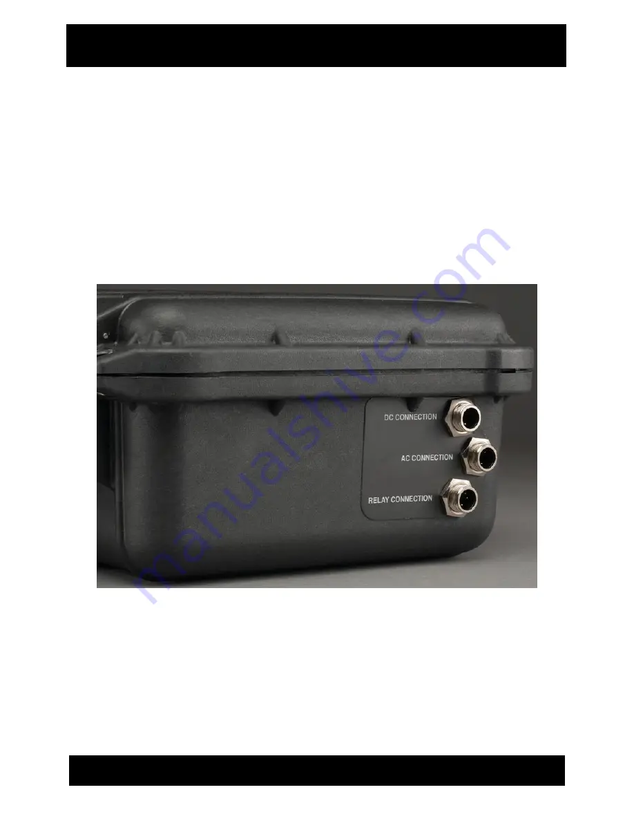
EXTERNAL CABLE PORTS 


AC Receptacle outlet to connect AC power cord. 


DC Connector outlet to connect DC power adapter. 


Two-Way  Relay  Connector  allows  the  system  to  activate  an  external  device,  and/or  to 
have an external device activate the system using an N/O or N/C contact. 


Summary of Contents for CENTURION SCOUT

Page 1: ...Response Technologies Ltd Centurion SCOUT Owner s Manual v2 Response Technologies Ltd CENTURION SCOUT OWNER S MANUAL PREVENT INJURIES DAMAGE or a SECURITY BREACH Read understand and follow this manual ...

Page 2: ...TEM DEPLOYMENT 6 SECTION 4 SYSTEM CONFIGURATION 7 ENTRY EXIT DELAY 7 RECORD MESSAGE 8 PLAY MESSAGE 8 SPEAKER ON OFF 8 LINK SENSOR 9 UNLINK SENSOR 9 PAIRED UNPAIRED 10 RESET ALL SETTINGS 11 INACTIVE TIME SCHEDULER 11 RELAY CONFIGURATION 12 SECTION 5 CONSOLE CONFIGURATION 13 CONNECT USING CONSOLE 13 HISTORY LOG 14 SAVE ARM 15 RESET DEFAULT CONFIGURATION 15 DATE TIME 15 INACTIVE TIME SCHEDULER 15 CON...

Page 3: ...ed and substance of the transmitted message help security personnel know instantly where assistance is needed as well as important facts about the location A variety of sensors such as motion detectors PIR duress buttons door window contacts smoke alarms and others may be used with the SCOUT The SCOUT utilizes leading edge technology and is manufactured to the highest standards of quality and exce...

Page 4: ...sely Install the SCOUT near an electrical AC outlet The AC power cord is your SCOUT s main AC disconnecting device and must be easily accessible at all times For your safety the power cord provided with your system has a grounded plug Always use the power cord with a properly grounded wall outlet to avoid the risk of electrical shock AVOID ELECTRIC SHOCK Disconnect all power sources by unplugging ...

Page 5: ...by activating sensors to confirm alert is being broadcast Immediately investigate and correct any issues including sensors that fail to respond properly Contact an authorized SCOUT technician for help with troubleshooting Testing should ALWAYS be performed after the initial configuration of the system after any changes to the system s configuration are made and as often as prescribed by your agenc...

Page 6: ...y interface with LED lights Battery status indicating LED lights Built in microphone for recording verbal message Built in speaker for listening to verbal message USB Port connector for USB communication to PC Recessed pinhole reset button for performing a hard reset Reset Button USB Port Microphone Speaker Battery Status LED Lights Touch Key Interface ...

Page 7: ...n 2 System Overview EXTERNAL CABLE PORTS AC Receptacle outlet to connect AC power cord DC Connector outlet to connect DC power adapter Two Way Relay Connector allows the system to activate an external device and or to have an external device activate the system using an N O or N C contact ...

Page 8: ...E EN N N L L LE E ED D D 6 6 67 7 7 9 9 99 9 9 b b ba a at t tt t te e er r ry y y p p po o ow w we e er r r l l le e ev v ve e el l l When system is turned OFF and charging a solid green LED indicates a full charge Note Store the unit plugged into an AC power source in order to maintain a full charge on the internal battery Internal battery will drain over a long period of time in storage SYSTEM ...

Page 9: ...v ve e el l l Y Y YE E EL L LL L LO O OW W W L L LE E ED D D 3 3 34 4 4 6 6 66 6 6 b b ba a at t tt t te e er r ry y y p p po o ow w we e er r r l l le e ev v ve e el l l G G GR R RE E EE E EN N N L L LE E ED D D 6 6 67 7 7 1 1 10 0 00 0 0 b b ba a at t tt t te e er r ry y y p p po o ow w we e er r r l l le e ev v ve e el l l The SCOUT will power up in the armed state The unit is armed and ready t...

Page 10: ...Delay press key three times to turn on Entry Delay and Exit Delay press key four times to turn off Entry Delay and Exit Delay Entry Delay Entry Delay is ON when ENTRY LED is lit Default Entry Delay is 30 seconds Selecting Entry Delay will transmit alert message in 30 seconds unless SCOUT is disarmed during the Entry Delay period Entry Delay time is configurable with provided Console software see C...

Page 11: ...th provided Console software see Console Configurations Section 5 Note To reset message back to the default alarm message press the RECORD MESSAGE key once and then immediately press the RECORD MESSAGE key again Keypad beep will sound once message has been reset Note Message recording will time out after 30 seconds if not saved User will need to record message again PLAY MESSAGE Press PLAY MESSAGE...

Page 12: ...low verbal prompts Press sensor reset button Voice prompt will confirm successful link Close sensor case Note Link Sensor will time out after 30 seconds if linking is not confirmed If time out occurs sensor will remain unlinked UNLINK SENSOR UNLINK SENSOR allows user to make a previously linked sensor no longer monitored by the SCOUT To unlink sensor Open sensor case small slotted screwdriver is n...

Page 13: ...red phone and play the user recorded message Speed Dial and Phone Number entries are configurable with provided Console software see Console Configurations Section 5 Device Pairing Press the PAIRED UNPAIRED key to place the SCOUT into pairing mode PAIRED UNPAIRED LED will blink slowly while waiting for device to be connected Follow the manufacturer s instructions provided with your phone to pair a...

Page 14: ...me press the current day of the week key and press the BEGIN TIME key repeatedly until the LED at the half hour mark closest to the current time is lit Press DAY TIME key to confirm 2 Press day of the week key Press the BEGIN TIME key to the desired start time of the period you want sensors to be inactive on that day Press END TIME key repeatedly until LEDs between start time and desired end time ...

Page 15: ...remains latched or until the system is disarmed The SCOUT must be off and the external device must be in its non alarm state when connecting the two input relay wires in order for the SCOUT to recognize the correct non alarm state when turned on GREEN WIRE Input ORANGE WIRE Input Output Relay The Output Relay allows the user to have the SCOUT activate any Normally Open or Normally Closed contact a...

Page 16: ...e computer With the SCOUT powered on connect the SCOUT to the computer using the provided USB cable Open the Console software to display the current SCOUT configuration Note The SCOUT USB port used for Console communication is located on the front edge of the front panel reference page 3 USB Port The USB port in the radio compartment is for maintaining a charge on a paired mobile device SCOUT Cons...

Page 17: ...ff SCOUT ARMED SCOUT armed and ready for sensor activation SCOUT DISARMED SCOUT disarmed and configurable SCOUT DATE TIME SET SCOUT system clock adjusted by user SCOUT OPERATING ON A C POWER SCOUT is running on AC power SCOUT OPERATING ON D C POWER SCOUT is running on internal or external battery SCOUT BATTERY LOW SCOUT system battery power is low SCOUT RESET TO DEFAULT CONFIGURATION SCOUT setting...

Page 18: ...is important when using SCOUT Inactive Time Scheduler see DATE TIME above Allows user to create a weekly schedule for all sensors excluding Duress Buttons and Bill Traps to be inactive Duress Buttons and Bill Traps linked to the system will not be affected by inactive times During inactive times system will process duress button and bill trap activations and ignore all other sensor activations Ent...

Page 19: ...nation determines amount of telephone number digits required i e local 5551212 long distance 15135551212 Speed Dial Select this option to have the paired cell phone dial a previously saved speed dial number upon sensor activation Enter the number assigned as the desired speed dial Bluetooth Volume Use the slide bar to set the desired output volume over the paired cell phone AUDIO OUTPUT Alert Tone...

Page 20: ...ith verbal notifications of internal back up battery status i e SCOUT battery low This section enables the user to turn on off battery notifications These notifications are transmitted via user s radio system paired cell phone or speaker This notification is only for the internal battery of the main SCOUT unit not sensors Entry Exit Delay Entry Delay field is used to set the delay 0 99 seconds for...

Page 21: ...ted or active low unselected The PTT Hold setting allows the user to configure the PTT setting between Hold PTT to Transmit selected or Release PTT to VOX unselected The Radio Always Powered setting allows the user to have the radio powered when the SCOUT is powered selected or to only power up during sensor activation notification unselected If this option is unselected a Radio Power Delay should...

Page 22: ...e page 15 in the Owner s Manual to manually change the time How do I change the recorded message for sensor activations See page 8 in the Owner s Manual to record the sensor activation message How do I link a sensor to the SCOUT See page 9 in the Owner s Manual to link or unlink sensors to the SCOUT Can I assign different messages to different sensors No The SCOUT has a single sensor activation me...

Page 23: ...mperatures ranging from 20 degrees Fahrenheit to 150 degrees Fahrenheit How long will the SCOUT run on internal battery When operating in temperature ranges between 65 and 80 degrees Fahrenheit the SCOUT can last up to 3 days Things that will negatively impact battery life include the following temperatures outside of range stated above number of sensors linked in range of the system number of ala...

Page 24: ...s in materials or workmanship for a period of one 1 year from the delivery date Please reference the SCOUT Limited Warranty certificate for complete details In order to obtain service under the warranty please contact Response Technologies Ltd at 365 Industrial Drive Harrison Ohio 45030 USA by telephone at 513 202 5500 or email info response technologies com ...

Reviews: