8
Make sure the following requirements are fulfilled:
The rolls, where the cells are placed, have to be made by a unique structure with fixed pins, where the self-aligning
bearings are set.
The rolls have to be dynamically balanced not to generate vibrations, which can affect the load cell signal.
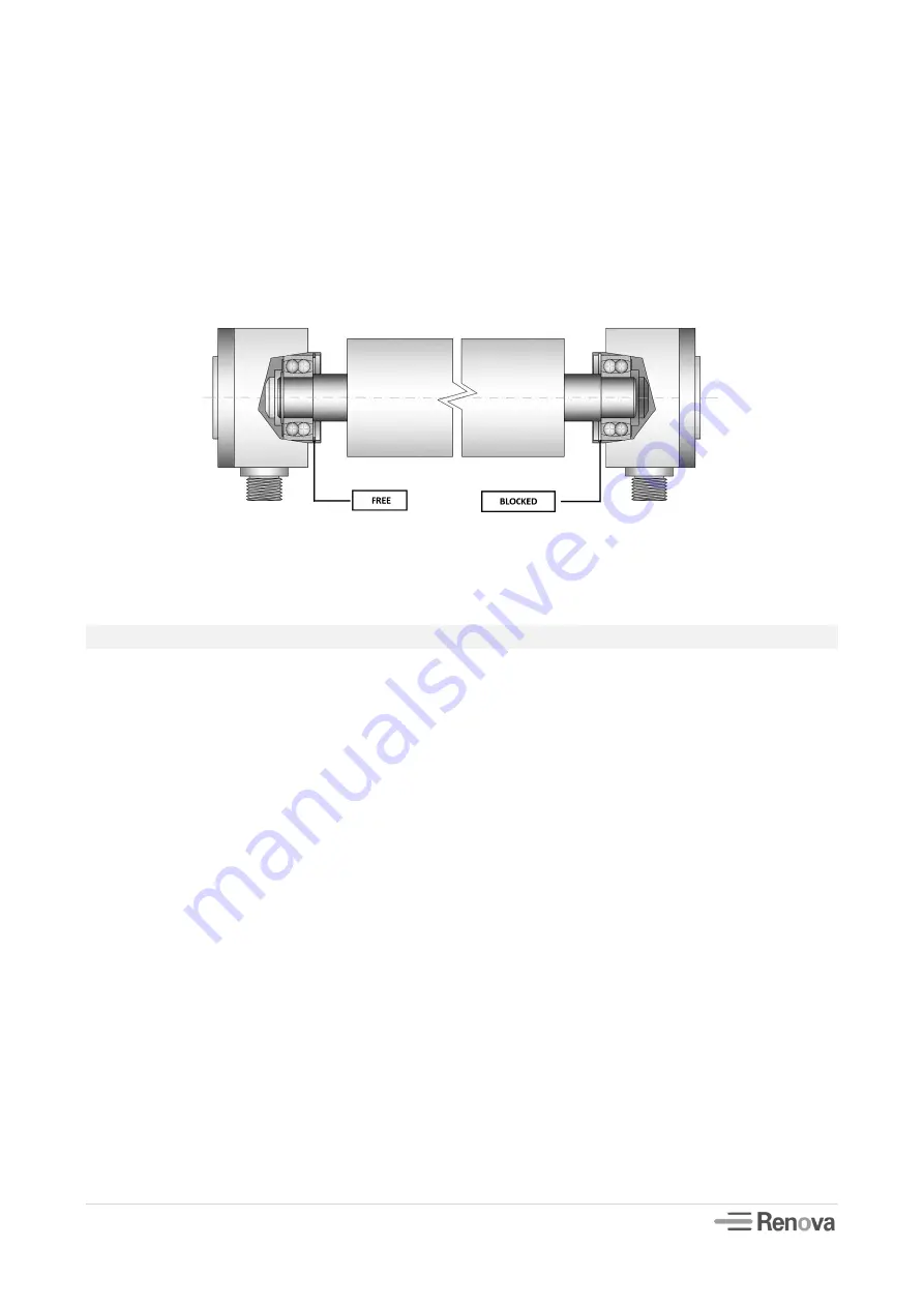
The rolls have to be axially locked only at one end, while at the other end they have to be free to slide. Figure 3
The length of the roll has to be design according to the selected load cell.
THROUGH SHAFT CELL SX-CH ASSEMBLING
Please, carefully follow these assembling steps:
Mount the cell with the arrow, printed on the body of the cell itself, oriented in the same direction of the resultant
of the forces acting on the load cell. Figure 2
Fix the flange of the cell onto the machine frame after checking the dimension of the centering and positions of the
screws. In case the project foresees the presence of two opposing load cells check their co-axiality. Lock firmly the
mounting screws, following the specified tightening torque for the required type of screw.
Pay attention in this operation because a mistake in the correct mounting may lead, in case of detachment of the
cells, to the break of the machine.
Make sure the following requirements are fulfilled:
The rolls, where the cells are placed, have to be made by a unique structure with fixed pins where the self-aligning
bearings are set.
The rolls have to be dynamically balanced not to generate vibrations which can affect the load cell signal.
The rolls have to be axially locked only at one end, while at the other end they has to be free to slide. Figure 3
The length of the roller has to be design according to the selected load cell.
Into the load cell body, two set screws are placed in order to regulate the maximum displacement of the sensor. The
position of these screws is calibrated and has not to be modified. If they are excessively screwed down, they limit
the deformation of the lamella, hence the strain gauges; on the other side, if they are too untighten, the
displacement of the lamella increases, so the risk of going above the yield strength of the material could overcome.
Figure 3


