Model BX-LP Operating Instructions
P/N 889-2902-00
4
VI
Warnings
For trouble free operation, use the Reno A&E model PLH (for pave over), or model PLB (for saw cut installation).
And follow good loop installation practices. The lead-in cable for each loop (including runs through all wiring
harnesses) must be twisted together a minimum of six (6) complete twists per foot. For trouble free operation, it is
highly recommended
that
all
connections (
including crimped connectors
) be soldered.
VIII Loop Installation
The vehicle detection characteristics of an inductive loop detector are greatly influenced by the loop size and
proximity to moving metal objects such as gates. Vehicles such as small motorcycles and high bed trucks can be
reliably detected if the proper size loop is selected. If the loop is placed too close to a moving metal gate, the
detector may detect the gate. The diagram below is intended as a reference for the dimensions that will influence
the detection characteristics.
General Rules
1. The detection height of a loop is 2/3 the
shortest leg (A or B) of the loop. Example:
Short leg = 6 feet, Detection Height = 2/3 x 6
feet = 4 feet.
A =
6 ft
9 ft
12 ft 15 ft 18 ft 21 ft
C =
3 ft
4 ft
4.5 ft
5 ft
5.5 ft
6 ft
2. As the length of leg A is increased, distance C
must also increase.
3. For reliable detection of small motorcycles,
legs A and B should not exceed 6 feet.
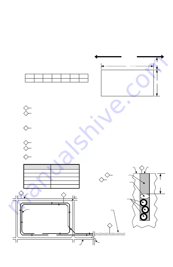
Loop Installation - Saw Cut Type
1
Mark the loop layout on the pavement. Remove sharp inside corners that can damage the loop wire insulation.
2
Set the saw to cut to a depth (typically 2" to 2.5") that ensures a minimum of 1" from the top of the wire to
pavement surface. The saw cut width should be larger than the wire diameter to avoid damage to the wire
insulation when placed in the saw slot. Cut the loop and feeder slots. Remove all debris from the saw slot with
compressed air. Check that the bottom of the slot is smooth.
3
It is highly recommended that a continuous length of wire be used to form the loop and feeder to the detector.
Loop wire is typically 14, 16, 18, or 20 AWG with cross-linked polyethylene insulation. Use a wood stick or roller
to insert the wire to the bottom of the saw slot (do not use sharp objects). Wrap the wire in the loop saw slot until
the desired number of turns is reached. Each turn of wire must lay flat on top of the previous turn.
4
The wire must be twisted together a minimum of 6 twists per foot from the end of the saw slot to the detector.
5
The wire must be held firmly in the slot with 1" pieces of backer rod every 1 to 2 feet. This prevents the wire from
floating when the loop sealant is applied.
6
Apply the sealant. The sealant selected should have good adhering properties with contraction and expansion
characteristics similar to those of the pavement material.
1
3
1/8" to 1/4" SAW SLOT
THE WIRE IS
CONTINUOUSLY WOUND
IN THE LOOP SAW SLOT
FOR THE REQUIRED
NUMBER OF TURNS (2
turns shown)
turn 2
turn 1
REMOVE SHARP
INSIDE CORNERS
FEEDER SLOT
END OF SAW CUT
4
THE WIRES MUST BE
TWISTED TOGETHER
6 TWISTS PER FOOT
FROM THE END OF
THE SAW CUT TO
THE DETECTOR
Recommended Loop Wire:
Reno A&E LW-120 for 1/8" slots
Reno A&E LW-116-S for 1/4" slots
ROAD SURFACE
MIN
1"
SAW SLOT
SEALANT
BACKER ROD
1" piece spaced
about every 1'
LOOP WIRE
3 TURNS
2
6
5
LOOP PERIMETER NUMBER OF TURNS
10 feet - 13 feet
5
14 feet - 26 feet
4
27 feet - 45 feet
3
46 feet - 100 feet
2
100 feet and up
1
C
A = Loop dimension parallel to the gate
B = Loop dimension perpendicular to the gate
C = Distance of the loop from the gate
SLIDE GATE
A
B


