Axis 0, Axis 1 and Axis 2 motor drive
connectors (7W2 'D' socket)
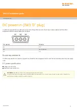
Each machine axis is connected to the SPA3-2 via a 7W2 socket
,
as shown below:
Pin number
Function
A1
Positive motor connection
A2
Negative motor connection
1
Positive tacho input *
2
Negative tacho input *
3
Screen (tacho)
4
Negative tacho input *
5
Screen (tacho)
Shell
Screen (motor)
The table shows the
default
polarity configurations for all pins, both motor output and the tacho feedback signals can be reversed in
UCCassist-2 during machine commissioning.
CAUTION:
Each SPA3-2 motor connection is capable of supplying up to 9.5 A peak at 80 V maximum. The actual peak current will
be dependent on the size of the motor fitted and the machine performance specification, therefore the cable size needs to be
calculated by the system installer or OEM.
* NOTE:
The motor tacho input supports a maximum differential input of ±100 V, tacho signals must be floating ﴾i.e. not connected
to ground or cable screen﴿. Single‐ended inputs can be used, however the maximum input in this configuration is ±18 V. It is
therefore recommended isolated tachometers are used.
SPA3-2 installation guide
www.renishaw.com
Issued 08 2020
34


