Renishaw FORTiS-S Functional Safety Installation Manual And Safety Manual Download Page 19

4

3

2

1

17

Original instructions

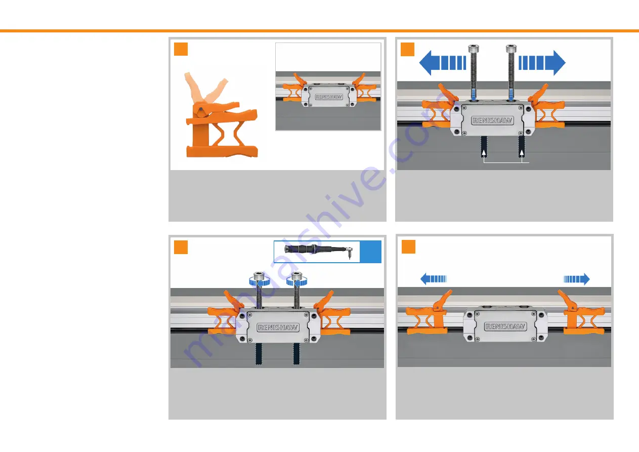
Set the alignment brackets to position 2.

Slide the readhead to align the readhead mounting holes to the machine 
slideway mounting holes.

Secure the readhead using 2 × M6 screws; tighten screws to a torque of 

8 Nm.

 Pull alignment bracket lever upwards into position 3 to open the alignment 
bracket. Slide the alignment brackets away from the readhead and remove 
from the extrusion.

NOTE:

 The alignment brackets must be removed after installation.

14.3.1  Installation using the alignment 

bracket method

2

Machine slideway 

mounting holes

3

4

1

8 Nm

Summary of Contents for FORTiS-S

Page 1: ...FORTiS S enclosed encoder system Functional Safety installation guide and safety manual Installation guide M 6725 9016 01 A...

Page 2: ...4 1 FORTiS S FS connector 9 10 Storage and handling 10 11 Installation drawings 11 11 1 Mounting surface preparation 11 11 2 Location edge or dowel pins 11 11 3 Mounting orientations 11 11 4 FORTiS S...

Page 3: ...n guide and safety manual which details the actions required for the safe integration of the FORTiS S FS encoder system with BiSS Safety or Siemens DRIVE CLiQ protocols as designated by the letter S i...

Page 4: ...ility of the end user to dispose of this product at a designated collection point for waste electrical and electronic equipment WEEE to enable reuse or recycling Correct disposal of this product will...

Page 5: ...the system manufacturer to set the evaluation unit to implement the appropriate actions when the FORTiS S FS encoder system reports an error The decision to use this system for the intended purpose is...

Page 6: ...RIVE CLiQ protocol lDU 1 70E 07 Architectural constraints Type B HFT 0 SFF 94 Hardware safety integrity compliance Route 1H Systematic safety integrity compliance Route 1S Systematic capability SC 2 D...

Page 7: ...nance of the system Resolution check Move the axis by a known distance and confirm that the position changes as expected The tolerance for raising a fault condition is relative to the safe position de...

Page 8: ...00B044SC36BS050X 02 Valid from Mod level 02 The product complies with EU directives The product complies with the following technical standards 2006 42 EC Machinery directive 2014 30 EU Electromagneti...

Page 9: ...e reduced In addition to enhanced breakage resistance the robust steel scale has a coefficient of thermal expansion similar to the base material used in the majority of machines reducing errors due to...

Page 10: ...tity Item Description FORTiS S FS encoder unit The FORTiS S FS enclosed encoder system 37 mm readhead setting shim Plastic shim to be used as an installation aid Air connection fitting To enable conne...

Page 11: ...m 1 m 3 m 6 m 9 m Encoder cable type D Armoured OD 10 mm 28 AWG 7 core Length options 1 m 3 m 6 m 9 m Extension cable type B OD 6 3 mm 23 AWG 6 core 3 twisted pairs single screen green jacket Length...

Page 12: ...ng 95 relative humidity non condensing to IEC 60068 2 78 Handling instructions Storage temperature 20 C to 70 C Operating temperature 0 C to 50 C IMPORTANT Handle very carefully to avoid damage to the...

Page 13: ...pared with a datum edge or aligned dowel pins to help locate the edge of the extrusion and ensure parallelism to the axis of motion 11 2 Location edge or dowel pins Dimensions and tolerances in mm 50...

Page 14: ...e connection either end 2 6 6 hole thru typ Either end X 0 1 0 05 A Recommended extrusion alignment pin locations if required Adjacent to first and last flexure holes plus every 300 500 mm C Compresse...

Page 15: ...6 536 1036 10 1040 1163 586 621 636 36 636 1136 11 1140 1263 636 671 36 636 1236 12 1240 1363 686 721 736 36 736 1136 13 1340 1463 736 771 36 736 1436 14 1440 1563 786 821 836 36 836 1563 15 1540 1663...

Page 16: ...flow rate to 2 l min Air quality see section 14 8 on page 24 for details Weight 0 27 kg 2 0 kg m Measuring standard Renishaw stainless steel scale with single track absolute encoding Coefficient of t...

Page 17: ...by aligning extrusion mounting holes Ensure the mounting faces are clean before installation If a suitable reference edge or dowel pins are not available then we recommend that the extrusion is check...

Page 18: ...der measuring length WARNING Failure to ensure the readhead is within the measuring length of the encoder could lead to a collision and damage 14 2 Start of measuring length S 19 5 1 ML KEY ML Measuri...

Page 19: ...ead using 2 M6 screws tighten screws to a torque of 8 Nm Pull alignment bracket lever upwards into position 3 to open the alignment bracket Slide the alignment brackets away from the readhead and remo...

Page 20: ...e installation Remove the setting shim 14 4 Set up shim method When using this method remove the alignment brackets see section 14 3 1 on page 17 just prior to installation Where access to the readhea...

Page 21: ...ve Place a section of the separated shim parts at either side of the readhead Whilst maintaining light pressure on the readhead secure the readhead with 2 M6 screws tighten screws to 8 Nm to complete...

Page 22: ...using the mounting aid method Remove alignment brackets prior to installation using the mounting aid When mounting a readhead to a machine slideway via an unconstrained bracket an installation mountin...

Page 23: ...Remove screws and nuts from mounting aid unlock and remove from extrusion Align readhead with the readhead mounting bracket and secure with M6 screws and nuts Using the correct tool tighten the screw...

Page 24: ...nd of the cable assembly must be less than 1 ohm Connector screw plug The cable connector port that is not being used should be fitted with the supplied screw plug 2 cable connector ports one either s...

Page 25: ...ed Diagnostic Tool for absolute encoders ADTa 100 LED status Description Required action BLUE Signal level is optimal No adjustment required GREEN Signal level is good No adjustment required ORANGE Si...

Page 26: ...trusion end caps Use a suitable air supply hose with a 4 mm bore WARNING Remove the blanking plug only from the position at which the purge air supply is to be connected or the sealing integrity may b...

Page 27: ...AWG 7 core single screen black jacket Flex life 20 106 cycles at 20 mm bend radius Minimum static bend radius internal radius 15 mm Type B OD 6 3 mm 23 AWG 6 core 3 twisted pairs single screen green...

Page 28: ...h the requirements for PELV of standard IEC 60950 1 X Over voltage protection 10 V Ripple 200 mVpp maximum frequency up to 500 kHz FORTiS S FS grounding and shielding BiSS C Customer electronics Exten...

Page 29: ...Wire colour Pin out M12 Power 5 V Brown 2 0 V White 5 8 Serial communications A Violet 3 A Yellow 4 Reserved Do not connect Grey 7 Pink 6 Shield Shield Cable braid Case The recommended tightening torq...

Page 30: ...ion and cyclic DRIVE CLiQ communication is taking place Orange Continuous light DRIVE CLiQ communication is being established Red Continuous light At least one fault is present in this component NOTE...

Page 31: ...nder Edge Gloucestershire GL12 8JR United Kingdom M 6725 9016 01 Part no M 6725 9016 01 A Issued 03 2021 For worldwide contact details visit www renishaw com contact Renishaw plc Registered in England...

Reviews: