Renishaw FASTRACK Installation Manual Download Page 15

13

QUANTiC RTLC40 / 

FASTRACK

 installation guide

System calibration

NOTE:

 The functions described below can also be carried out using the optional ADTi-100 and ADT View software. See 

www.renishaw.com/adt


for more information.

Before system calibration:

u


Clean the scale and readhead optical window.

u


If reinstalling, restore factory defaults 

(‘Restoring factory defaults’, page 14)

.

u


Maximise the signal strength along full length of travel (readhead set-up LED is flashing Green).

NOTE:

 Maximum calibration speed 100 mm/s or less than the readhead maximum, whichever is slowest. 

Step 1 – Incremental signal calibration

u


Cycle the power to the readhead or connect the ‘Remote CAL’ output pin to 0 V for < 3 seconds. The readhead will then single flash Blue to indicate it is in calibration mode as detailed in 

‘Readhead mounting and alignment’, page 12

The readhead will only enter calibration mode if the LED is flashing Green.

u


Move the readhead at slow speed along the axis ensuring it does not pass a reference mark, until the LED starts double-flashing indicating the incremental signals are now calibrated and the new settings are stored in 

the readhead memory. 

u


The system is now ready for reference mark phasing. For systems without a reference mark, cycle the power to the readhead or connect the ‘Remote CAL’ output pin to 0 V for < 3 seconds to exit calibration mode.

u


If the system does not automatically enter the reference mark phasing stage (LED continues single flashing) the calibration of the incremental signals has failed. After ensuring failure is not due to overspeed (> 100 mm/s, 

or 

exceeding the readhead maximum speed), exit the calibration routine, restore factory defaults as detailed below, and check the readhead installation and system cleanliness before repeating the calibration routine.

NOTE:

 For analogue variants of QUANTiC ensure correct termination of output signals 

(‘Recommended signal termination’, page 19)

.

Step 2 – Reference mark phasing

u


Move the readhead back and forth over the selected reference mark until the LED stops flashing and remains solid Blue. The reference mark is now phased.

NOTE:

 Only the chosen reference mark that has been used in the calibration routine is guaranteed to remain phased. 

u


The system automatically exits the calibration routine and is ready for operation.

AGC and AOC are automatically switched on once calibration is complete. To switch off AGC refer to 

‘Switching Automatic Gain Control (AGC) on or off’, page 14

.

u


If the LED continues double-flashing after repeatedly passing the chosen reference mark it is not being detected. 

  Ensure that the correct readhead configuration is being used. Readheads can either output all reference marks or only output a reference mark where a reference selector magnet is fitted depending on the options 

chosen when ordering.

  Check reference mark selector magnet is fitted in the correct location relative to readhead orientation 

(‘RTLC40 / FASTRACK installation drawing’, page 4)

.

Calibration routine manual exit

u


To exit the calibration routine at any stage cycle the power to the readhead or connect the ‘Remote CAL’ output pin to 0 V for < 3 seconds. The LED will then stop flashing. 
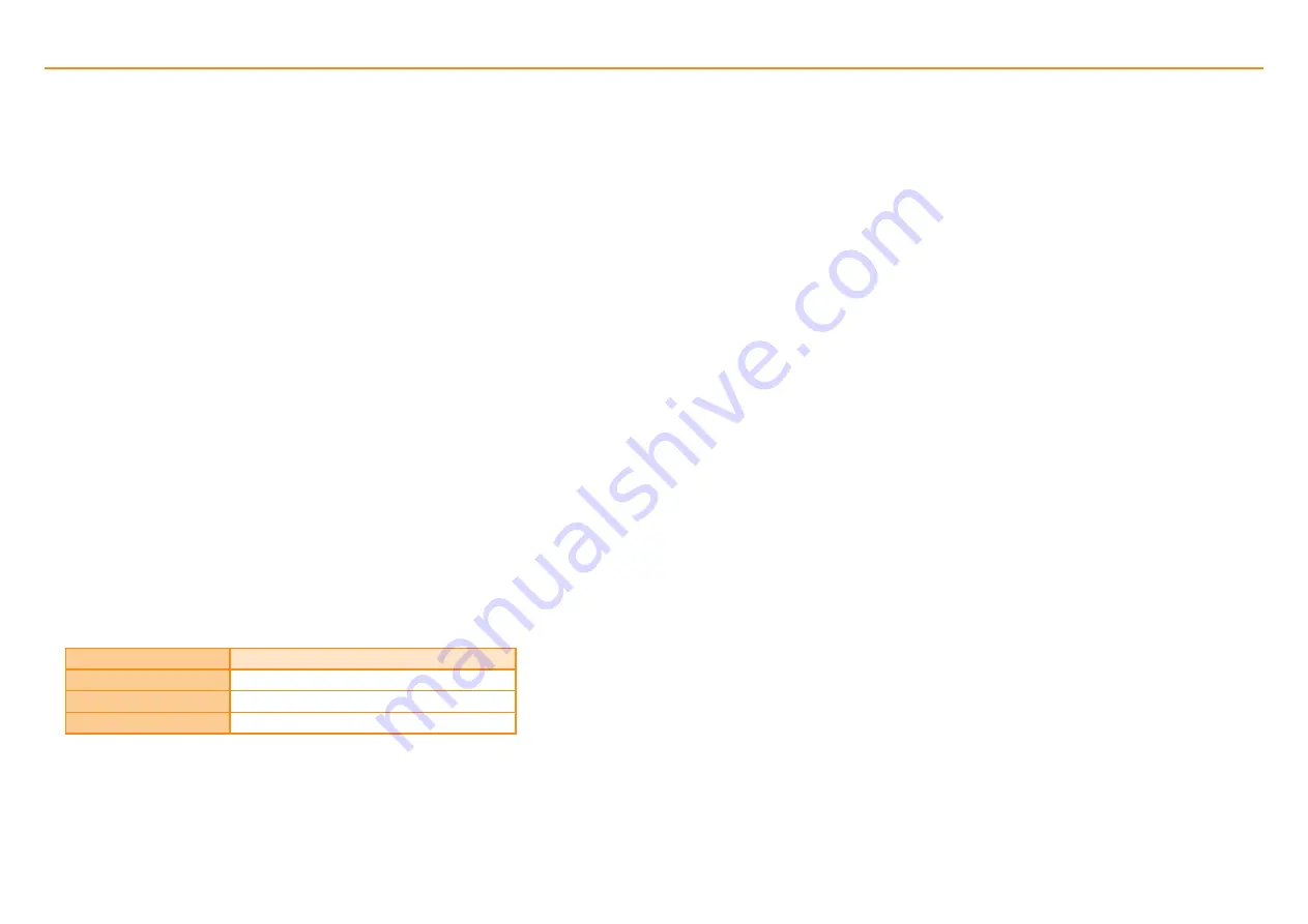
LED

Settings stored

Blue single flashing

None, restore factory defaults and recalibrate

Blue double flashing

Incremental only

Blue (auto-complete)

Incremental and reference mark

Summary of Contents for FASTRACK

Page 1: ...Installation guide M 9417 9248 03 A QUANTiC RTLC40 FASTRACK incremental linear encoder system...

Page 2: ...ark selector and limit magnet installation 10 QUANTiC quick start guide 11 Readhead mounting and alignment 12 System calibration 13 Restoring factory defaults 14 Switching Automatic Gain Control AGC o...

Page 3: ...the following two conditions 1 This device may not cause harmful interference and 2 this device must accept any interference received including interference that may cause undesired operation The use...

Page 4: ...TE Ensure self adhesive tape is on the outside of bend 95 relative humidity non condensing to IEC 60068 2 78 2013 Humidity Storage 70 C 0 C Operating Storage and handling N heptane CH3 CH2 5CH3 Propan...

Page 5: ...10 Static bend radius 35 23 11 5 Optical centreline marker 4 2 5 0 2 5 2 mounting holes M2 5 through counterbored 3 2 3 deep both sides NOTE The recommended thread engagement is 5 min 7 5 including co...

Page 6: ...STRACK length 100 mm The reference mark selector and limit actuator locations are correct for the readhead orientation shown External magnetic fields greater than 6 mT in the vicinity of the readhead...

Page 7: ...ge and handling page 2 u Centre section removal tool A 9589 0122 u Small pair of pliers u Dial Test Indicator DTI u Protective gloves Optional parts u Renishaw scale wipes A 9523 4040 u Lint free clot...

Page 8: ...as shown and place guillotine press block down onto the FASTRACK scale Ensure the block is in the correct orientation as shown Whilst holding the block in place in a smooth motion pull down the lever...

Page 9: ...age centre section removal tool and with consistent forward pressure remove centre section If the ledge method or similar is used then the appropriate side panel on the removal tool will need to be re...

Page 10: ...de RTLC40 FASTRACK scale system application continued Ensure a gap 1 mm 7 Clean FASTRACK and scale using a lint free cloth 6 Optional fix self adhesive end covers ensuring a gap of at least 1 mm betwe...

Page 11: ...and FASTRACK so it wicks underneath adjacent to user selected datum location as shown NOTE Drawing shows the scale datum adjacent to the chosen reference mark NOTE When reference mark and datum clamp...

Page 12: ...e bracket should be sufficiently stiff so that it is able to tolerate such force without distorting Following the clamping instructions on the scale installation will prevent this magnetic force from...

Page 13: ...mory at power down NOTE If calibration fails LED remains single flashing blue restore factory defaults by obscuring the readhead optical window on power up page 14 Repeat the installation and calibrat...

Page 14: ...imise signal strength in challenging installations See www renishaw com adt for more information NOTE When re installing the readhead factory defaults should be restored page 14 Green Orange Red flash...

Page 15: ...ed 100 mm s or exceeding the readhead maximum speed exit the calibration routine restore factory defaults as detailed below and check the readhead installation and system cleanliness before repeating...

Page 16: ...nnect the Remote CAL output pin to 0 V u Power the readhead u Remove the spacer or if using the connection from the Remote CAL output pin to 0 V u The LED will start continuously flashing indicating f...

Page 17: ...system page 13 Can t initiate the calibration routine Signal size is 70 u Realign readhead to obtain a green flashing LED During calibration the LED on the readhead remains single flashing Blue even a...

Page 18: ...as been calibrated for referencing your system as only this reference mark will be guaranteed to remain phased u Clean the scale and readhead optical window and check for scratches then recalibrate th...

Page 19: ...imits P Pink 11 8 A 14 Q Black 10 6 B 13 Alarm E Orange 3 13 F 3 Remote CAL CAL Clear 9 1 5 C 4 Shield Screen Case Case Case Case Ferrule Digital outputs Function Signal Colour 15 way D type L 15 way...

Page 20: ...24 24 24 18 13 7 25 3 626 1 813 25 1 40 24 24 24 14 50 5 80 2 900 1 450 31 6 25 24 24 18 13 9 06 3 63 1 813 0 906 51 0 20 24 24 16 11 8 06 3 22 1 611 0 806 57 5 12 24 24 10 36 5 18 2 07 1 036 0 518 9...

Page 21: ...24 V R Vp Vq P Q Select R so that maximum current does not exceed 20 mA Alternatively use a suitable relay or opto isolator Remote CAL operation CAL 0 V IMPORTANT The shield should be connected to the...

Page 22: ...duration of the signal period is available Contact your local Renishaw representative for more information Digital output signals Form Square wave differential line driver to EIA RS422A except limits...

Page 23: ...Hz to 2000 Hz 3 axes Mass Readhead 9 g Cable 26 g m EMC compliance IEC 61326 1 Readhead cable Single shielded outside diameter 4 25 0 25 mm Flex life 20 106 cycles at 30 mm bend radius UL recognised c...

Page 24: ...ss steel Mass 24 g m Coefficient of thermal expansion at 20 C 10 1 0 2 m m C Installation temperature 15 C to 35 C Mounting Self adhesive backing tape Reference mark Type Customer selected IN TRAC ref...

Page 25: ...0 1453 524901 E uk renishaw com www renishaw com For worldwide contact details visit www renishaw com contact Part no M 9417 9248 03 A Issued 12 2020 M 9417 9248 03 Renishaw plc Registered in England...

Reviews: