


AN1899 Rev 0.00
Page 8 of 24
January 8, 2014
HIP2103-4DEMO1Z
The current monitor output, I
motor
, digitized by the
microcontroller, can be used to control the torque of the motor or
to limit the battery recharging current during regenerative
braking. Because of the offset voltage on the current monitor
output, signals above 1.65VDC represents positive motor current
and signals less that 1.65VDC represent negative motor current.
(Note that this hardware feature is provided for customer
evaluation but is not implemented in the microcontroller
firmware.)
The output voltage of the differential amplifier is (with
superposition):
where I
M
is the bridge current (motor current),
R3||R4 = R11||R12, and (R14+R17) = (R15+R18) (as required
for the diff- amp topology).
Using the defaults values of the HIP2103-4DEMO1Z, Equation 1
simplifies to:
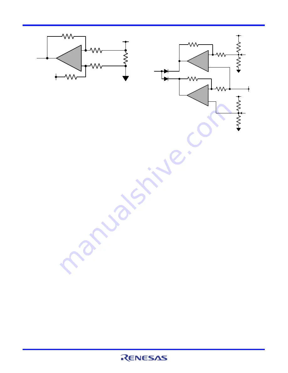
The I
motor
signal is monitored by two comparators. See
Figure 11. The output of the upper U3 comparator is biased to go
low when the positive motor current exceeds ~ 20A. Conversely,
the output of the lower comparator is biased to go low when the
negative motor current exceeds ~-20A.
The OR’ed outputs of these two comparators is monitored by the
microcontroller. Pulse-by-pulse current limiting is provided on
each negative transition. After 256 consecutive pulse limits, all
the bridge FETs are permanently turned off and the current limit
alarm LED (led3) is turned on.
There are two different methods to change the pulse-by pulse
current limit. The easiest method is to change the value of the
current sensing resistors R23 and R24. For example, removing
R24 halves the pulse by pulse current limit to ±10A while not
affecting the full scale I
motor
output signal.
Equation 3 calculates the value of the current sensing resistors to
set the pulse-by-pulse current limit at a desired level without
changing the full scale output voltage swing of the I
motor
signal.
This equation assumes that the only change made to the
HIP2103-4DEMO1Z is modifying the values of the current
sensing resistors R23 and R24.
For example: for Ilimit = ±5A,
R21||R22 = [(1.65-.188)V /(16.2K /1.661K)] / 5)
R21||R22 = 0.030
Ω
An alternative method for changing the pulse-by-pulse current is
to change the gain of the diff-amp.
For example, if it is desired to decrease the current limit to 10A
without changing the current sense resistors, R21 and R22, the
gain of the diff-amp can be increased. Equation 4 illustrates this
method that reduces the value of R17 (and consequently R18) to
increase the gain of the diff-amp.
Equation 4 sets the positive current limit bias voltage.
Because the diff-amp topology requires symmetry, R18 must
also be changed to 320.
In the above examples both the positive and negative current
limit value are equal in absolute values. It is acceptable to have
different limits for the positive and negative values.
FIGURE 10. THEVENIN EQUIVALENT DIFFERENTIAL AMPLIFIER
Vout
CS
= (R3||R4)/(R14+R17) x (R21||R22) x I
M
+(R15+R18)/[R11||R12+(R15+R18)] x
[(R3||R4)+(R14+R17)]/(R14+R17) x 1.65V
(EQ. 1)
Vout
CS
= [16.2K /1.661K] x (.0075) x I
M
+ 1.661K/(16.K+1.022K) x (16.2K+1.611K)/(1.611K)x 1.65V
or
Vout
CS
= 0.07315 x I
M
+1.65V
(EQ. 2)
U2
R14+R17
R15+R18
R3||R4
R11||R12
1.65V
thev
ISL28246FUZ
16.2K
16.2K
1.611K
1.611K
Note that resistors labeled Rx||Ry
represent a parallel equivalent resistor
of Rx and Ry. Rx+Ry represents the
series combination of Rx and Ry.
R21||R22
from
bridge
.0075
I
motor
+
-
FIGURE 11. PULSE-BY-PULSE CURRENT LIMIT COMPARATORS
R21||R22 = [(1.65-.188)V /(16.2K /1.661K)] / Im)
(EQ. 3)
R17 = (R3||R4)/[(1.65-.188)V / (R21||R21 x 10A)] - R14.
or
R17 = 16.2K/[1.462V/(.0075 x 10A)] - 511 = 320
(EQ. 4)
U3
R4
R1
R12A
ISL28246FUZ
10K
604
+
-
R38
3.3V
U3
R11
R39
R12B
ISL28246FUZ
10K
+
-
R11B
3.3V
1M
1M
10K
10K
604
Imotor
to
microcontroller
.188V
3.3V-.188V