AN1899 Rev 0.00
Page 2 of 24
January 8, 2014
HIP2103-4DEMO1Z
The Hall inputs section is the terminal connections from the
BLDC motor for the hall sensors and the 3.3V bias for the
sensors.
The phase A, B, and C sections include the HIP2103/4 drivers,
bridge FETs, and power terminal connections for the motor.
For those customers who would like to modify the firmware of
the PIC18F2431 microcontroller, an RJ11 connector is provided
for easy connection with Microchip firmware development tools
(not provided or supported by Intersil).
Block Diagram
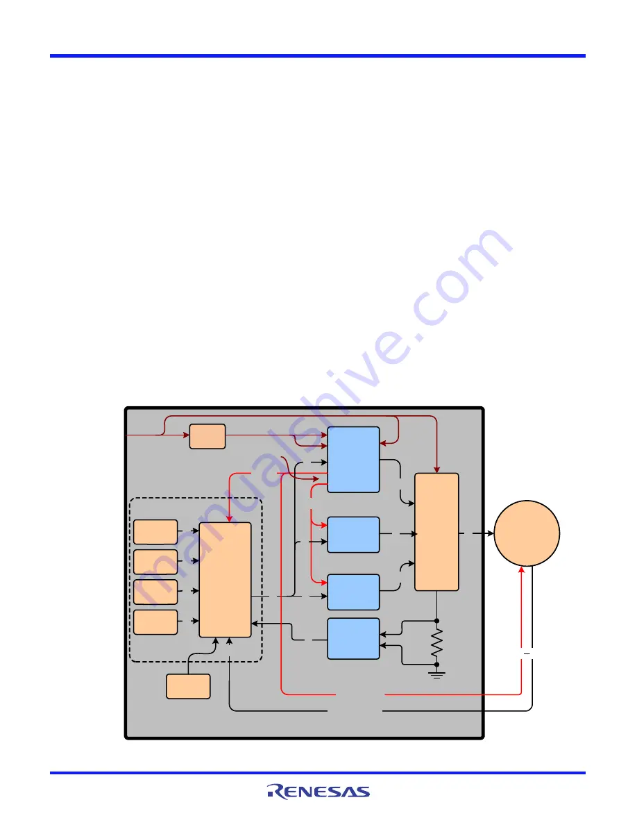
The HIP2103-4DEMO1Z is composed of seven major circuit
function illustrating the use of several Intersil products. The
following descriptions reference Figure 2.
Bias Supplies
Two bias supplies are required and are provided by one HIP2104
driver with internal linear regulators. The VCC output (3.3V) of the
HIP2104 provides the bias to the controller, Hall sensors, and
LEDs. The VDD output (12V) of the HIP2104 provides its own bias
for its driver portion and also to the other two HIP2103s (which
do not have internal regulators).
HIP2103 and HIP2104 Drivers
The one HIP2104 and the two HIP2103s are the featured Intersil
parts. Each driver’s outputs (HO and LO) are connected to a half
bridge pair of SiR662DP-T1-GE3 power FETS operating with a
PWM frequency of 20kHz. Associated with the HIP2103s and
HIP2104 are the necessary support circuits such as the
decoupling and boot capacitors.
Controller
The microcontroller is located on a daughter card to provide the
customer with the option to incorporate their own controller
design. The features on the controller daughter card are
configuration dip switches, status LEDs, a programming port,
and 4 push-buttons.
The Hall sensor inputs are decoded by the microcontroller to
provide the appropriate switching sequence signals to the 3
HIP2103/4s to drive the six bridge FETs that drive a 3-phase
BLDC motor. The SW5 dip switch is used to select the appropriate
switching sequence for the BLDC motor.
With appropriate setting to the SW6 dip switch, the motor driver
can be configured with a full bridge topology for bidirectional
control of a conventional brushed DC motor. A half bridge option
is also provided to drive a brushed DC motor without bidirectional
control. See Table 1 for more details on configuring SW6.
In addition to decoding the Hall sensors, the microcontroller
reads the push buttons to invoke the various operating functions
of the motor, and controls the status LEDs.
The microcontroller firmware is provided for reference but the
only support offered by Intersil will be for bug corrections and for
FIGURE 2. HIP2103-4DEMO1Z BLOCK DIAGRAM
HIP2103-4DEMO1Z REV. A
HIP2104
CONTROLLER
PUSH
BUTTONS
13-50V
3-PHASE
BRIDGE
ISL28246
CURRENT
LIMIT
AND
MONITOR
3
2
3
VDEN
SWITCH
HIP2103
Vcc
Vdd
6
2
2
2
2
2
4
3.3V
3
2
DIP
SWITCHES
8
LEDs
4
HIP2103
12V
VDen
VCen
VBAT
BLDC
MOTOR
Hall Bias
HALL INPUTS
2
DAUGHTER CARD
PROGRAM
PORT
2
SPEED
CONTROL
Bias supplies
are internal to
the HIP2104


