background image

18 

11. Now tighten the bolts using 2 hexagonal wrenches 

that have a large enough opening. 

12. Use a second wrench to apply counterpressure 

when tightening. 

13. Insulate the installed refrigerant lines including the 

connector against heat.         

Only use insulation hoses sealed against diffusion 
that are suitable for this temperature range.


14. Connect the condensation and control lines.        

If you also need a condensation pump, install it be-
forehand. 

15. If it is not possible to run the condensation line 

through the same guideway, make sure that the 
condensation can drain freely at all times.


16. Lay the refrigerant lines from the indoor unit to the 

outdoor part.     

Make sure that they are adequately secured. Take 
steps, if necessary, to ensure oil recirculation! 

17. Place the control line in the same line guideway. 
18. Remove the protective caps supplied and the swivel 

nut caps of the shut-off valves and use these for 
continued assembly. 

19. Before you flare the refrigerant lines, ensure that 

there is a swivel nut on the hose.     

Only use the factory-installed swivel nuts.


20. Connect the refrigerant lines to the outdoor part as 

described above. 

G


If the length of the connection line is longer than 5 
m, refrigerant must be added to the system during 
initial operation. 

See the section Adding Refrigerant. 

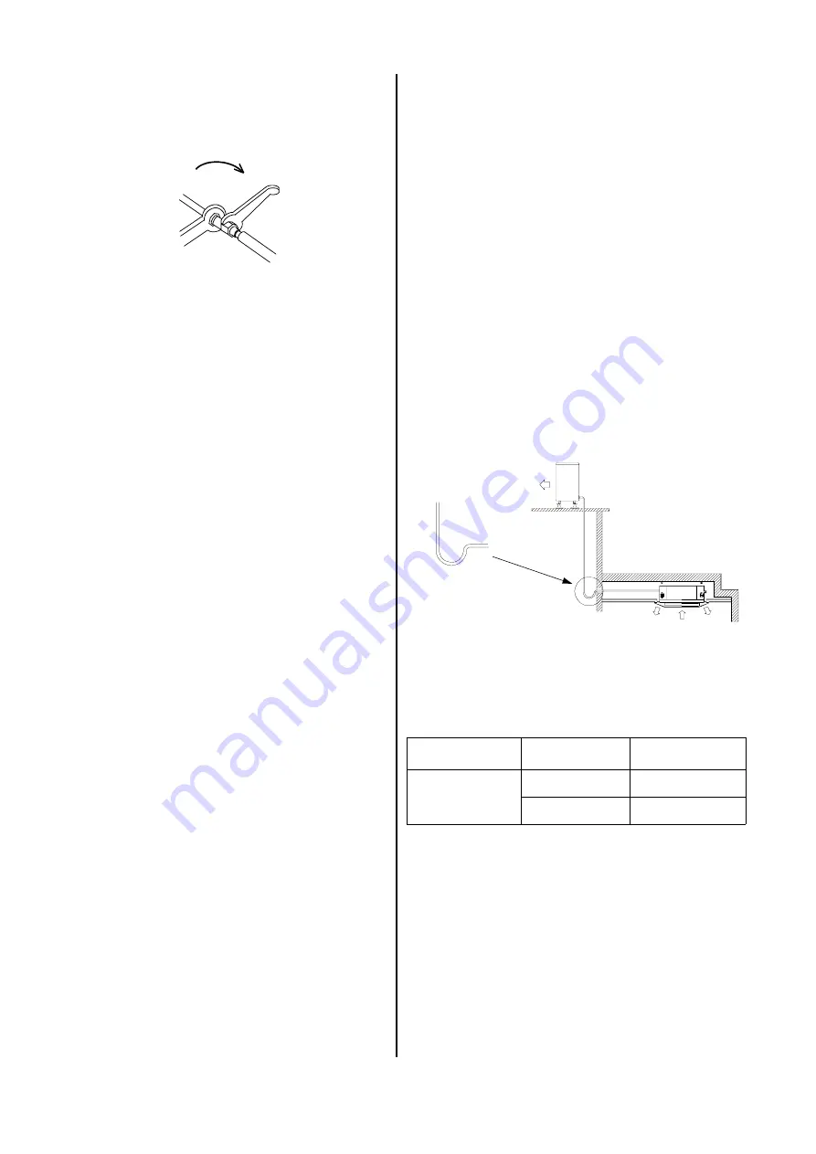
Oil recirculation 

If the outdoor part is set up at a higher level than the in-
door unit, appropriate steps must be taken for oil recir-
culation. 
This is usually accomplished by creating an oil elevation 
arc that is installed every 2.5 meters of line going up. 

Impermeability test 

Once all connections have been made, the manometer 
station is connected to the corresponding valve connec-
tions as described below: 
           blue = large valve = suction pressure, 
After the connection has been made, an impermeability 
test is conducted using dry nitrogen. 
The connections that have been established are 
sprayed with a leak locator spray to test for imperme-
ability. If bubbles appear, the connection was not made 
properly. Tighten the bolts more firmly or, if necessary, 
create a new flare. 
After the impermeability test has been successfully con-
ducted, any excess pressure is removed from the refrig-
erant lines and the vacuum pump put into operation to 
create a vacuum in the lines. 

We recommend using a two-speed vacuum pump with 
an absolute final partial pressure of at least 0.01 mbar 
at a pump capacity of a min. of 1.5 m³/h.


Procedure: 
1. Remove the vacuum pump and connect the filling 

cylinder or the refrigerant container. 

2. Place the open cylinder/container on a scale and 

calibrate the scale to zero. 

3. Create a vacuum in the hose at the height of the ma-

nometer distribution pipe. 

4. Determine the required amount based on the infor-

mation in the table above and open the suction pres-
sure side of the manometer to begin the filling proc-
ess. 

5. Close the manometer valve when the appropriate 

amount has been added. 

Length of the line 

Diameter of the  

injection line 

Additional quantity 

per m 

5 m up to and  

including a max. 

of 15 m 

9.52 mm Ø 

3

/

8


‘‘ 

18 g for RKS


9.52 mm Ø 

3

/

8


‘‘ 

30 g for RKM


Adding refrigerant 

The additional refrigerant amount required is based on 
the length (5 m and higher) and the diameter of the 
pressure line. 

Counterpressure 

open-end wrench 1


Counterpressure


open-end wrench 2


G


A vacuum with a minimum of 0.05 mbar must be 
created!


How long it takes to create the vacuum is based on the 
hose line volume of the indoor unit and the length of the 
refrigerant lines. However, this process takes a mini-
mum of 30 minutes. 
Once foreign gases and moisture have been completely 
removed from the system, the manometer station 
valves are closed and the valves of the outdoor part are 
opened.


Radius  
min. 50 mm 

Oil elevation arc in the 
suction line to the outdoor 
part 1x for every 2.5 m 


Outdoor part 

Indoor unit 

Summary of Contents for RKV 13 C

Page 1: ...REMKO powerful like a bear REMKO RKV 13 C 18 C 24 C Ceiling Cassettes Edition GB P05 Operation Technology Spare Parts...

Page 2: ......

Page 3: ...sonnel 16 Installation 17 Condensation Connection 19 Electrical Connection 19 Two Room and Fresh Air Connection 21 Prior to Initial Operation 22 Initial Operation 22 Certification for Initial Operatio...

Page 4: ...indoor unit and the remote control from moisture Protect all electric cables and connection lines from being damaged for example by animals Protect the air conditioning unit and the remote con trol fr...

Page 5: ...at the polarity is correct when inserting the batteries Use the labelling in the slot Close the battery slot again Once the reset button 20 see page 12 is pressed the remote control is ready for opera...

Page 6: ...sor of the fan is defective or outside of its regu lation range Blinks 4 times The frost protection mechanism has been activated Blinks 10 times EEPROM defective Green light ON OFF signal It lights up...

Page 7: ...he unit does not switch off this process must be re peated Switching the unit on Button 7 If the air conditioning unit is to be switched on only the clock may be visible on the remote control display...

Page 8: ...mbol appears on the display M Cooling mode In this operating mode the room in the air is cooled and slightly dehumidified The following section Temperature selection buttons describes how to set the d...

Page 9: ...late fins can be set to The air outlet plate fins are set for oscillat ing air distribution Symbols on the display The positions and settings of the air outlet plate fins are represented by the follow...

Page 10: ...orresponding symbol disappears from the dis play 3 Remember if the unit is already switched on it is only possible to program another start up time The current settings of the unit are transferred for...

Page 11: ...s 5 Press the button 6 repeatedly until UCFG ap pears on the display 6 Press either the button 8 or 9 to change the preset from heating pump HP to air conditioning unit AC 7 Press the button 13 to tra...

Page 12: ...and then press the 7 button to quit the configuration menu G If no button is pressed for 30 seconds the configu ration menu is automatically exited and program ming must be started from the beginning...

Page 13: ...e to the bottom Customer Service and Guarantee For the guarantee to be valid the purchaser or his cus tomer must completely fill out the guarantee certificate enclosed with all units and send it back...

Page 14: ...ia control line outdoor part Power consumption W 75 80 105 Current consumption A 0 4 0 4 0 5 Fan capacity W 63 68 93 Fan speeds 3 automatic 3 automatic 3 automatic Air volume current per speed m h 550...

Page 15: ...hade Electromagnetic fields are disrupt ing transmission Does the unit work when devices in the vicinity are switched off No signal transmission when sources of disruption are operated simultaneously...

Page 16: ...bjects that emit intense heat e g lights Install it in the middle of the room instead Wall lead throughs Wall lead throughs are necessary to establish the con nection between the indoor unit and the o...

Page 17: ...on mount and the bottom of the intermedi ate ceiling see figure above Connect the refrigerant control and condensation lines to the indoor unit as described below and check again hat the unit is posit...

Page 18: ...t is conducted using dry nitrogen The connections that have been established are sprayed with a leak locator spray to test for imperme ability If bubbles appear the connection was not made properly Ti...

Page 19: ...door unit the system must be cur rent free The electrical connections of the indoor unit and the ter minals of the control line to the outdoor part are located on the regulating panel The regulating p...

Page 20: ...utral conduct External conduct No function Protection conduct Wiring diagram RKV 13 C Main board Fan motor Micro float regulator Condensation pump LED IR connection Plate fin motor and micro plate fin...

Page 21: ...nit To do this use a black strip with ad hesive on one side which is stuck to the opening s to be sealed The strip must be able to withstand the strain from the air pressure permanently The flanged co...

Page 22: ...indicate operation 3 Connect the unit to the power supply and switch the power on 4 Press down the buttons 9 and 13 of the re mote control for five seconds The display is deleted The letters Src for a...

Page 23: ...re The following must be performed measured validated during initial operation Test Visible check setup assembly of outdoor part and indoor unit s OK problem Visible check of the heat exchanger OK pro...

Page 24: ...REMKO GmbH Co KG Klima und W rmetechnik D 32791 Lage Im Seelenkamp 12 D 32777 Lage PO Box 1827 Phone 49 5232 606 0 Fax 49 5232 606260 E Mail info remko de Internet www remko de...

Reviews: