REMKO PWL 101-3 Operation,Technology,Spare Parts Download Page 10

10

REMKO PWL

Set the switch of the respective 
control unit to the „Off“ or „0“ 
position.

Precautions for extended periods 
of non-use 

   Disconnect the electrical con-

nection in all poles.

   Shut-off the hydraulic connec-

tion.

   Where there is a risk of frost, 

the entire system must be 
drained if no suitable antifreeze 
agent has been added to the 
heating medium (water). 

(See also page 9)

Decommissioning

Care and maintenance

ATTENTION

It does not suffice to switch off 
the unit only via the switch!

During initial commissioning

During initial commissioning, all 
regulating, control and safety 
devices must be checked for their 
proper functioning and correct 
adjustment. 

   The power consumption of the 

fan must be measured.  

The nominal current must not 
exceed the values on the rating 
plate at the respective opera-
ting speeds. 

   Check the motor protection 

function of the fan.

   Check the complete system for 

de-energised installation and 
possible vibrations. 

   Check the heating/cooling 

medium supply pipes for correct 
connection, tightness and insu-
lation. 

 It must be ensured that no more 

condensate is produced as in 
this case the condensate pump 
is also disconnected from the 
supply and no longer operatio-
nal.

   Wait for the fan to stop.

    Shut-off the water circuit and 

lock to prevent unauthorised 
opening.

   Allow the fin heat exchanger to 

cool down.

Cleaning the units

   The surfaces of the units must 

be cleaned only dry or with a 
moist cloth and a small amount 
of soap solution if necessary.

   Under no circumstances use 

high-pressure cleaners or steam 
jet equipment to clean the 
mounted unit.

   Do not use caustic cleaning 

agents or those containing 
solvents.

   Only suitable cleaning agents 

must be used even to remove 
heavy fouling.

   Clean all air inlets and air outlet 

louvres.

   Clean the fan impeller. If ne-

cessary, remove the motor or 
protection grille.

   Clean the heat exchanger fins 

either by blowing out, suction 
or with a soft brush.

The units generally require no 
maintenance. The units and fin 
exchanger surfaces must be vi-
sually inspected every six months 
and before the start of the heating 
period. 
In dust-laden environments, the 
units must be inspected at shorter 
intervals. 

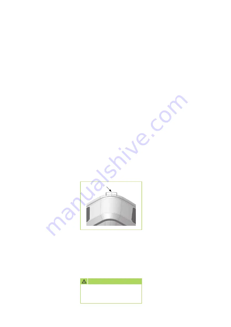
For this purpose, the cover of the 
unit must be detached from the 
supporting part of the unit by re-
moving the 3 securing clips at the 
corners. 
For inspection purposes, the cover 
must be held under the supporting 
part with the aid of holding straps.  
The cover can be removed com-
pletely from the unit if required by 
loosening the strap adjuster on the 
holding straps.

During removal, it must be en-
sured that the suction hose and 
condensate pump sensor are also 
disconnected from the supporting 
part.

Securing clip

Important precautions to be taken 
prior to all maintenance

    The units must be disconnected 

from the supply in all poles and 
locked to prevent unauthorised 
reconnection.

Summary of Contents for PWL 101-3

Page 1: ...Edition GB Vo6 REMKO PWL Ceiling mounted air unit Heating Cooling Operation Technology Spare parts...

Page 2: ......

Page 3: ...ta PWL 201 203 16 Rating tables Technical data PWL 301 303 18 Intended use 20 Customer service and warranty 20 Environmental protection and recycling 20 Exploded view 21 Spare parts list 21 Legend Ope...

Page 4: ...s length width height Required air change Required room temperature Required heating medium tem perature for flow and return The air inlet temperature of the units should not be below 34 C and not abo...

Page 5: ...r removal of the produced condensate in cooling operation a ready to connect condensate pump is provided For an optimal air flow individually adjustable louvres are provided at the top of the housing...

Page 6: ...o an air outlet temperature of 8K below room temperature and ideal prima ry air flow conditions Maximum mounting heights and operating limits The maximum mounting heights depend on the maximum range a...

Page 7: ...using This prevents persons being expo sed to a direct air stream Rooms with low ceilings horizontal blowing direction Rooms with low ceilings horizontal blowing direction Rooms with high ceilings ver...

Page 8: ...day night control etc can always be connected per control unit Terminals in the unit Fuse protection in the supply to the control unit must be in compli ance with the applicable regulati ons The conn...

Page 9: ...tion To prevent frost damage anti frost protection must be provided at temperatures below 0 C Where systems in rooms at risk from frost are not used for ex tended periods under no circum stances must...

Page 10: ...ool down Cleaning the units The surfaces of the units must be cleaned only dry or with a moist cloth and a small amount of soap solution if necessary Under no circumstances use high pressure cleaners...

Page 11: ...hydraulic con nection 4 Remove the bottom support plate 6 screws 5 Remove the support plate with fin exchanger downwards 6 Carefully re install the replace ment heat exchanger and all further componen...

Page 12: ...he produced con densate in cooling operation The pump is a self priming rotary diaphragm pump The condensate is pumped out via a flexible PVC condensate hose with an internal diameter of 6 mm Safety i...

Page 13: ...red Unit dimensions Dimen sions PWL 101 103 HK PWL 201 203 HK PWL 301 303 HK A 985 mm 1084 mm 1178 mm B 632 mm 963 mm 1043 mm C 229 mm 229 mm 229 mm D 989 mm 1073 mm 1160 mm H 465 mm 485 mm 504 mm Con...

Page 14: ...8 34 11 6 36 16 4 41 14 2 42 20 6 9 30 6 1 31 11 0 37 10 0 39 14 2 45 12 3 44 70 50 C 0 12 0 16 10 7 18 19 5 28 17 8 31 25 4 37 22 0 40 5 10 8 20 9 7 21 17 6 30 16 1 33 23 0 39 19 9 42 10 9 7 24 8 6 2...

Page 15: ...0 24 54 4 5 23 55 7 8 20 67 7 0 19 69 10 5 17 77 9 3 16 79 32 40 5 9 25 55 5 3 25 56 9 2 21 67 8 3 20 69 12 3 18 77 10 8 16 79 8 14 C 24 60 2 5 21 71 2 3 21 72 4 1 19 80 3 7 18 81 5 9 17 86 5 3 16 88...

Page 16: ...7 5 33 15 5 34 22 5 38 19 8 40 20 8 4 28 7 5 29 15 1 35 13 4 37 19 4 40 17 1 42 70 50 C 0 14 5 13 13 0 14 26 6 25 23 7 27 34 5 34 30 4 36 5 12 9 17 11 6 18 24 1 28 21 4 30 31 2 36 27 4 38 10 11 4 21 1...

Page 17: ...74 12 3 17 76 32 40 6 4 27 53 5 8 26 54 12 3 22 65 11 2 21 67 16 1 19 74 14 4 18 76 8 14 C 24 60 2 2 22 68 2 0 22 69 5 6 19 79 5 1 19 80 7 2 18 85 6 5 17 86 26 50 2 8 23 59 2 5 23 60 5 9 20 73 5 2 20...

Page 18: ...9 30 14 9 33 29 2 37 16 5 43 20 10 9 28 8 2 29 17 8 33 12 8 36 25 2 39 14 3 45 70 50 C 0 18 8 12 14 3 15 31 0 21 22 3 26 44 8 32 25 6 41 5 16 9 16 12 7 19 27 8 24 20 0 29 40 5 34 23 2 43 10 14 9 20 1...

Page 19: ...8 15 81 32 40 8 3 27 52 6 5 26 55 13 0 23 63 10 0 22 68 29 1 19 73 12 7 16 81 8 14 C 24 60 3 0 22 68 2 3 21 70 8 4 17 81 3 6 19 79 9 4 18 84 6 0 16 89 26 50 3 7 23 58 2 8 23 61 8 5 18 74 4 4 20 70 9 9...

Page 20: ...a valuable contribution towards waste reduction and the conservation of raw materials Only dispose of packaging materi al at the facilities provided Disposal of old unit The production of our units is...

Page 21: ...2 speed 1110706 1110717 1110728 6 Top support plate 1110707 1110718 1110729 7 Bottom support plate 1110708 1110719 1110730 8 Side air grille 1110709 1110720 1110731 9 Bottom air segment 1110710 11107...

Page 22: ...With the external rotor motor the impeller with its drive motor is an optimal unit for applications in the field of heating and ventilation The axial flow fan is statically and dynamically balanced Th...

Page 23: ...750 920 750 Air capacity Bg 1 m3 h 2030 1685 3110 2580 4300 2650 Air capacity Bg 2 m3 h 1960 1610 2900 2400 4150 2400 Air capacity Bg 3 m3 h 1885 1530 2580 2350 3900 1710 Sound pressure level LpA 1m 1...

Page 24: ...t as advisers to our customers in air conditioning and heating technology SFlbCustomer Service Our equipment operates precisely and reliably However in the event of a fault REMKO customer service is q...

Reviews: