


6
Maintenance
Depending on the operation conditions the units are to
be tested by an expert when necessary, but at least re-
gularly every two years, to ensure their safe operation.
The test result is to be recorded in a test certificate
which is to be safely kept until the next test so that it
can be presented to the authorized persons for control
purposes at any time.
The persons charged with the operation of the units
have to check the units before starting work to detect
obvious defects on the operating and safety elements
and to make sure that the safety devices have not been
removed.
If any faults are stated the supervisor is to be informed.
If the faults affect the unit’s operational reliability, opera-
tion is to be stopped!
l
Regular maintenance and care, at least after each
heating period is the basic condition for a long ser-
vice life and a faultless operation of the unit.
l
Make sure to keep the unit free from dust and other
deposits and to clean it only with a dry or humid cloth
(do not use water jet).
l
Do not use sharp or solvent-containing cleaning
agents.
l
Check the suction opening for combustion air as well
as the injector fitted behind it and the gas nozzle re-
gularly to make sure that they are not dirty.
l
Clean gas burner and gas nozzle regularly.
l
Clean baffle plate regularly.
l
Check suction and blowing out lattice regularly to see
whether it is dirty and clean it, when necessary.
When the unit is being maintained, set or repai-
red, the gas supply has to be cut off and the
mains plug has to be unplugged from the mains
socket!
Setting and maintenance work is to be carried
out only by authorized specialists!
Any operation/handling which does not corre-
spond to that indicated in these instructions is
prohibited, otherwise we will not be responsi-
ble and the guarantee will become void!
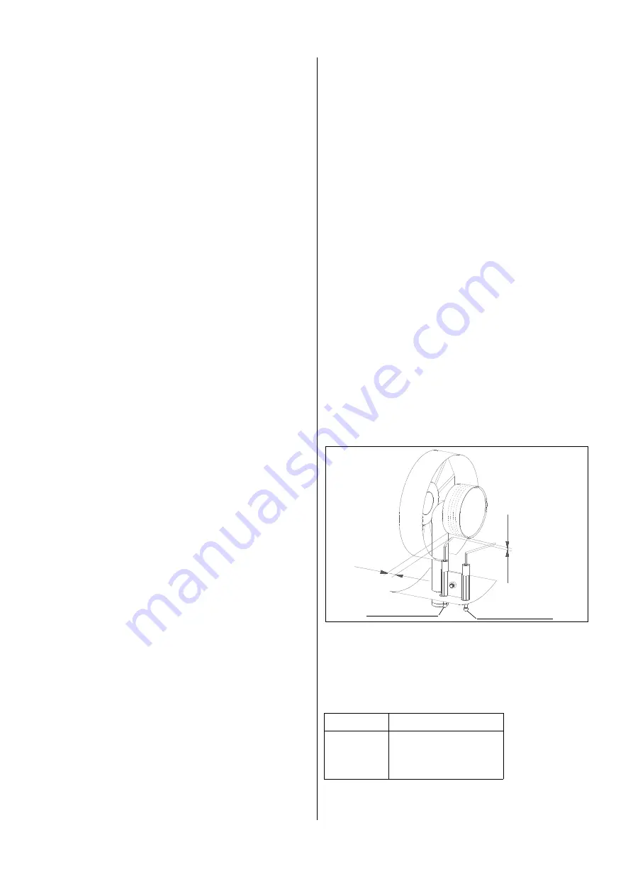
Setting hints:
Dim. A = distance from ignition electrode tip to burner
Dim. B = distance from ignition electrode tip to burner
type A B
PGT 30 3 15
PGT 60 3 15
PGT 100 4 30
G
A
ionisation electrode
B
ignition electrode
Removal and Cleaning of the Gas Burner
l
Remove protective exhaust lattice and outer casing
and disassemble inspection cover from the lower
side of the unit.
l
Loosen clamping screw of nozzle holding device.
l
Pull ignition cable from initiating electrode.
l
Remove ionisation cable from ionisation electrode
(attention domed cap nut and lock washer).
l
Loosen clamping screw of electrode holder, pull out
initiating electrode and ionisation electrode.
l
Unscrew 4 fastening screws of the burner and take
burner out of the unit.
l
Clean burner with steel brush and compressed air
and reassemble in reverse order.
l
Set initiating electrode and ionisation electrode
according to the instructions given below.
l
Reassemble all the parts carefully in reverse order.
l
Carry out functional control of the whole unit and
tightness control of all gas bearing connections
with soap solution and leakage detection spray,
respectively.
l
An intensive yellowish flame indicates insuffi-
cient fresh air supply and pollution within the
unit, respectively.
G
G
approx. dimensions in mm


