Air Handling units AeroMaster XP
27
Section Description
The case for built-in electrical elements is integrated into the 1000
mm long modular XP through section. The section casing is designed
as a standard XP unit section (sandwich panels with inner 50 mm
insulation) and equipped with a hinged service door.
All case parts are made of 1 mm thick bent steel sheets galvanized
with a 275 g/m2 zinc layer. The internal fixing elements are made of
2.0 mm steel sheets. The case parts are spot welded and sealed with
silicone sealant.
To increase air auto-convection, the case is provided with inlet (lower)
and outlet (upper) ventilating apertures for inlet and outlet of air
coming through the XP unit. The ventilating apertures are protected
against water by a labyrinth cover (IP44) and against dust by a
replaceable filter insert (EU3).
The outdoor version is completed with protective elements against
weather effects (optional accessories of the AeroMaster XP air-
handling unit).
Electrical wiring, interconnection of individual parts, initial inspection,
operation and maintenance must be performed in accordance with
applicable standards and regulations.
Creating and maintaining conditions - the temperature - for proper
operation of individual components, is an essential factor for outdoor
installations of the XP section equipped with the control unit.
Therefore, it is necessary to use additional accessories for heating
or cooling. These accessories are delivered in accordance with the
operating conditions specified in the project (using AeroCAD software)
for which the designer is responsible.
Instructions for Cabling
A set of frequency converters up to 2 × 18.5 kW + 1 x 0.37 kW output
can be installed in the XPRF section (depending on the XP unit
size).
All interconnections of the distribution board and installed ele-
ments must be made using intact double insulated cables which
must be properly dimensioned for the given load and lead length.
Every cable leading out from the section must be led through
the preinstalled cable grommets. All unused grommets must be
blinded to maintain the degree of protection.
When connecting and leading the cables, it is necessary to take
into account their properties. The conductors must not be exposed
to strains which decrease their service life. Avoid cable slack;
always use cable protectors and trenches (wire, plastic, or metal)
of sufficient size and length. Properly fix all cables and keep to
minimum bending radiuses.
The M&C cable lines must be led separately from the power cables
to avoid their interference. We recommend leading the power
cable lines along the base frame and the M&C cable lines along the
front edge of the top panel.
The cable lines must never interfere with the service panels (doors),
removable panels (e.g. panel with handles, exchanger outlet panel,
etc.) or obstruct routine operation and servicing. Please respect
the reserved servicing space.
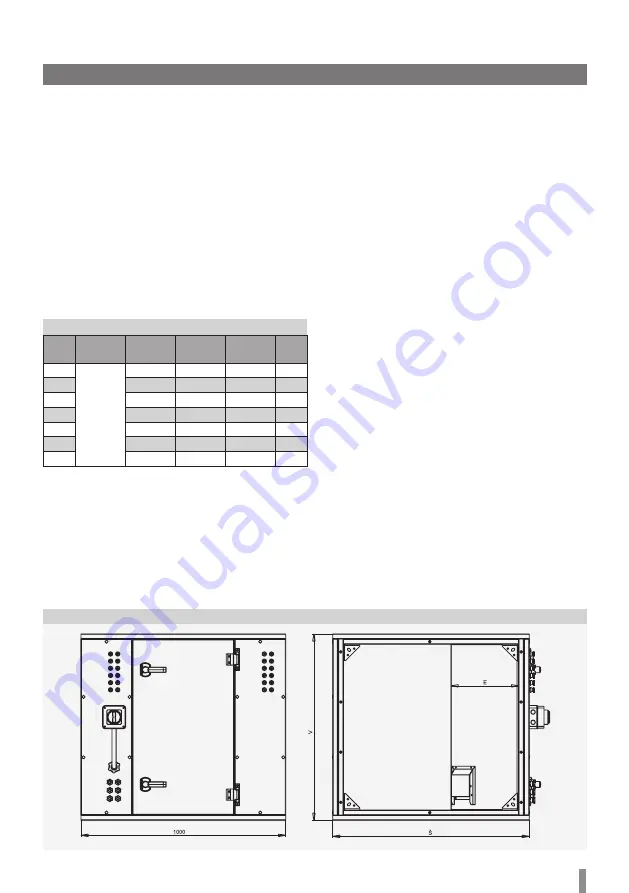
Figure 1
- Basic dimensions of the section
Table 1
– Basic dimensions of XPRJ / XPRF sections
XPRJ and XPRF Sections
Size
L (mm)
W (mm)
H (mm)
E
m
(kg)*
XP 04
1000 mm
650
600
230
84
XP 06
800
750
230
103
XP 10
960
910
330
125
XP 13
1065
1015
330
138
XP 17
1370
1015
330
154
XP 22
1370
1320
330
177
XP 28
1675
1320
330
193
* Weight of empty section
Installation Instructions, Operation and
Maintenance
XPRJ and XPRF Sections are designed to be installed in the AeroMaster
XP air-handling unit assembly. For packaging, transport, handling and
installation, refer to „Goods Despatch“ and „Installation“.
Staff qualification requirements: installation, connection, commis-
sioning, repairs and maintenance can only be performed by properly
qualified personnel.


