background image

installation


Grandview

®

 G800C-1 Gas Fireplace  |    67

Log Set Installation

11.22.19

920-127a

LOG SET INSTALLATION

Page 1 of 4

1

Rear Log

2

Middle Left Log

3

Middle Right Log

4

Center Left Cross Log

5

Front Bottom 'Y' Log

6

Left Rear Log

7

Right Cross Log

8

Middle Front

9

Left Log Piece

10

Right Log Piece

11

Left Front Log Piece

12

Right Front Log Piece

Must also purchase (#761-938) Log 
Grate and Ember package separate-
ly. The kit contains:

Log Grate

3/4" Ginger glass

Vermiculite

Black/White Embers

Log Support Plates


Read the instructions below carefully and refer to the diagrams.  
If logs are broken do not use the unit until they are replaced. 
Broken logs can  interfere with the pilot operation.

The G800EC/G800C/G800C-1  log sets, #761-930 for Oak, #761-932 
for Birch, contain the following pieces:

1

6

8

2

3

4

9

11

5

10

12

7

NOTE: Panels (brick, steel, or enamel) must be installed 

prior to installing the log set.

1.  Carefully remove the logs from the box and unwrap them.  The logs 

are fragile, handle with care - 

do not force into position when 

installing.

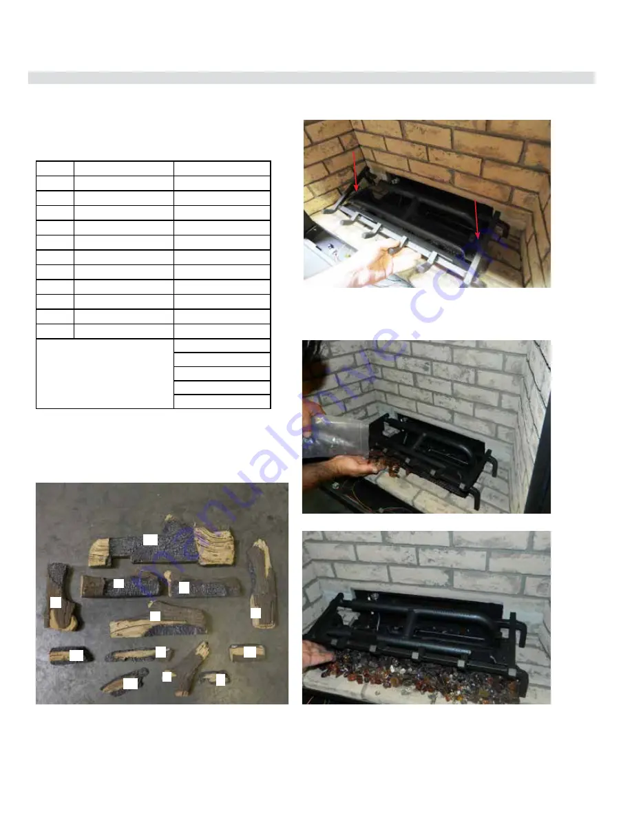
2. Install the log grate—secure with 2 screws in locations show below.

3.  Install the supplied crystals over the ember lights underneath the 

burner as  shown. Place vermiculite and embers on top of the glass. 
Do not place any media on the burner.

Diagram 1—Log ID

Diagram 2—Log Grate Install

Diagram 3—Install Glass

Diagram 4—Install Vermi Lava

G800EC/G800C/G800C-1 

Summary of Contents for Grandview G800C-1

Page 1: ...eave the building immediately Immediately call your gas supplier from a neighbour s phone Follow the gas supplier s instructions If you cannot reach your gas supplier call the fire department Installation and service must be performed by a qualified installer service agency or the gas supplier Installer Please complete the details on the back cover and leave this manual with the homeowner Homeowne...

Page 2: ...vided with this appliance and must be installed for the protection of children and other at risk individuals DANGER 920 408 CAUTION HOT WHILE IN OPERATION DO NOT TOUCH SEVERE BURNS MAY RESULT KEEP CHILDREN CLOTHING FURNITURE GASOLINE AND ANY OTHER LIQUIDS WITH FLAMMABLE VAPOURS AWAY KEEP BURNER AND CONTROL COMPARTMENT CLEAN SEE INSTALLATION AND OPERATING INSTRUCTIONS ACCOMPANYING APPLIANCE Front L...

Page 3: ... current National Electrical Code ANSI NFPA 70 in the U S A and the current CAN CGA B149 Gas Installation Code and the current Canadian Electrical Code CSA C22 1 in Canada This appliance comes equipped with a dedicated 8 Ground Lug for attachment of the ground wire to the steel chassis as applicable to local codes The appliance when installed must be electrically grounded in accordance with local ...

Page 4: ...d other spaces of the building 4 Close fireplace dampers 5 Turn on clothes dryers and any appliance not connected to the venting system Turn on any exhaust fans such as range hoods and bathroom exhausts so they are operating at maximum speed Do not operate a summer exhaust fan 6 Follow the lighting instructions Place the appliance being inspected into operation Adjust the thermostat so appliance is...

Page 5: ...tion 12 Lighting the Pilot Using the Gas Control Knob Extender 13 Copy of Lighting Plate Instructions 14 Operating Procedure for Optional Remote Control Part 761 976 15 Safety Screen Removal 16 Safety Screen Installation 16 Glass Door Removal 16 Glass Door Installation 16 Gas Installation Checklist 9 Installation Checklist 17 Locating Your Gas Fireplace 17 HeatWave Duct System Optional Kit 946 556...

Page 6: ... 2 9 WC C E 0 72kPa 53 DMS 14 500 Btu h 4 25kW 26 500 Btu h 7 77kW 0 4500 ft pi 0 1372 m Minimum supply pressure Manifold pressure high Manifold pressure low Orifice size Minimum input Maximum input Altitude This appliance must be installed in accordance with local codes if any if none follow the National Fuel Gas Code ANSI Z223 1 or Natural Gas and Propane Installation Code CSA B149 1 This applia...

Page 7: ...ctly in line with the exhaust vent terminal for the horizontally vented gas fueled heating appliance or equipment The sign shall read in print size no less than one half 1 2 inch in size GAS VENT DIRECTLY BELOW KEEP CLEAR OF ALL OBSTRUCTIONS 4 INSPECTION The state or local gas inspector of the side wall horizontally vented gas fueled equipment shall not approve the installation unless upon inspect...

Page 8: ... 8 924mm 35 1 8 892mm 18 7 8 480mm 17 1 2 446mm 7 1 2 192mm 1 1 2 39mm 28 7 8 734mm 11 1 4 287mm 11 1 4 287mm ELECTRICAL INLET 4 101mm 6 5 8 170mm 18 457mm 19 481mm NON COOL WALL 16 7 8 429mm COOL WALL 7 5 8 195mm 1 1 4 32mm 32 1 2 823mm FIREPLACE OPENING GAS INLET 37 3 4 959mm 34 3 4 883mm 37 1 2 953mm 34 5 8 880mm Finishing Trim Faceplate 29 737mm Note Gas connection is from the left hand side o...

Page 9: ...erted to top or rear vent per manual instructions and the insulation discarded Venting YES NO Are the venting components approved for the unit installed Does the venting configuration comply with venting diagrams Is venting installed and secured and are clearances for the vent pipe and termination cap maintained If applicable was a 1 4 rise maintained for every foot of horizontal run Was the termi...

Page 10: ...r shutter on the proper setting after running the unit for 20 minutes If applicable were the surround and trims installed according to the manual Was the operation of the fan lights if installed and flame modulation checked Customer Tutorial and Presentation YES NO Is the customer confident operating the new gas appliance and aware of all the features on the remote Confirm that the rating and ligh...

Page 11: ...OUT OF THE ROOM AND AWAY FROM HOT SURFACES ANY SAFETY SCREEN GUARD OR BARRIER REMOVED FOR SERVICING THE APPLIANCE MUST BE REPLACED PRIOR TO OPERATING THE APPLIANCE IF THE BARRIER BECOMES DA M AG E D T H E BA R R I E R SHALL BE REPLACED WITH THE MANUFACTURER S BARRIER FOR THIS APPLIANCE A BARRIER DESIGNEDTO REDUCE THE RISK OF BURNS FROM THE HOTVIEWING GLASS IS PROVIDED WITH THIS APPLIANCE AND SHALL...

Page 12: ...g the appliance 8 To prevent injury do not allow anyone who is unfamiliarwiththeoperationtousethefireplace 9 Wear gloves and safety glasses for protection while doing required maintenance 10 Be aware of electrical wiring locations in walls and ceilings when cutting holes for termination 11 Under no circumstances should this appliance be modified Parts that have to be removed for servicing should b...

Page 13: ...low Cradle Extender Knob 2 Slide the extender knob over the pilot on off knob located on the gas valve See below 3 Follow instructions on how to light the pilot in this manual or the lighting plate located on the underside of the unit 4 Once the pilot is lit remove the extender knob and put it back into the cradle for future use On off pilot knob on gas valve Extender knob slid over on off pilot k...

Page 14: ...ur de l appareil pour déceler une odeur de gaz Reniflez au niveau du plancher car certains gaz sont plus lourds que l air et peuvent s accumuler au niveau du sol QUE FAIRE SI VOUS SENTEZ UNE ODEUR DE GAZ Ne tentez pas d allumer l appareil Ne touchez à aucun interrupteur n utilisez pas de téléphones se trouvant dans le bâtiment Sortez du bâtiment immediatement Appelez immédiatement votre fournisseu...

Page 15: ...the high position A single acoustic signal from the receiver confirms the reception of the command Low Battery Detection Transmitter Thedurationoftheremotecontrolbatteriesdepends on many factors the quality of the batteries used the number of ignitions of the appliance etc If the transmitter batteries are low the light intensity of the LED see Fig 5 will decrease when you press the ON OFF key to a...

Page 16: ...nstallation Glass Door Removal 1 To install the door Reverse steps above 1 To remove the glass door place both hands on either side of the latch Pull forward then up to unlock repeat on opposite side Important After releasing the latches support the weight of the door 2 With both latches released support the door with both hands and tilt out to approximately a 60 degree angle 3 Lift the door up an...

Page 17: ... gas connections Test the pilot Must be as per Diagram Refer to Pilot Adjustment section Convert to propane if desired Refer to Gas Line Installation and Conversion Kit from NG to LPG sections 5 Make electrical connections to receptacle sup plied with unit recommended 6 Install standard and optional features Refer to the following sections a Standard Glass Door b Rear to top vent conversion c Cool...

Page 18: ...ation 16 Cool Wall installation Cool Wall Conversion 17 Cool Wall Clearances 18 Cool Wall Mantel Clearances 19 Cool Wall Mantel Leg Clearances 19 Cool Wall Installation Framing 20 Chase Venting 21 Chase Vent Installation Cool Wall 22 Clean Front Installation Non Cool Wall Clearances 23 Clean Front Installation Non Cool Wall Mantel Clearances 24 Clean Front Installation Non Cool Wall Mantel Leg Cle...

Page 19: ...ible Installation Clean Front Standard Install Non vented chase Non combustible board required Combustible framing Cool Wall Install Vented chase Combustible material can be used all around the fireplace Combustible framing Clean Front Clean Front Outside Finish w Finishing Trim Outside Finish w Faceplate ...

Page 20: ...nit and discard 3 Slide out tab as shown to remove recycle part 4 Insert a large slotted screwdriver into the slot in between front and back tabs bend the three 3 tabs up 90 towards the front DO NOT REMOVE TABS 5 Bend the rear three 3 tabs up 90 towards the back of the unit 6 Flip top panel 180 and reinstall to top of unit with four 4 screws in loca tions shown below ...

Page 21: ...t min 0 Top of Fireplace Opening B Sidewall 6 152 mm Side of Fireplace Opening C Ceiling 47 1 2 1207 mm Top of Fireplace Opening D Mantel Depth max 14 356 mm Front of Fireplace Opening E Alcove Width 84 2134 mm Wall to Wall Minimum F Alcove Depth 36 914 mm Front to Back Wall Maximum G Convection Air Outlet 66 sq 426 cm2 Top Front of Enclosure H Convection Air Outlet Opening Offset 0 2 51 mm Top of...

Page 22: ... B C From Top of Fireplace Opening 32 1 2 826 mm 10 254 mm 5 127 mm Combustible Mantel Clearances 2 0 12 6 4 8 10 0 Top of Fireplace Opening A B 14 To Floor 10 Inches 5 C 2 7 14 Mantel leg Allowable mantel leg projection TopView Side opening of fireplace Mantel leg Mantel leg 2 51mm 3 76mm 1 3 4 44mm 32 3 4 832mm overall fireplace width Clean finish 6 152 mm 5 127 mm Cool Wall Mantel Leg Clearances S...

Page 23: ...ht requires consideration of the hearth height Dimension N N the thickness of the installed hearth Q P R M N O S S U T V Combustible header Top Vent Rear Vent W Corner Top Vent Only IMPORTANT Corner applications are vented from the top only rear venting cannot be used Note The 2 standoffs at the rear of the appliance may be removed as these are not required in this application Ensure that any scre...

Page 24: ...s Minimum height of enclosure from base of appliance is 80 2032 mm CHASE VENTING A minimum 66 in2 opening in the enclosure is required to maintain safe operating temperatures This can be achieved in a number of ways including the examples shown below Warning DO NOT cover or place objects in front of the air outlet s Regency Chase Vent Custom chase vent Reveal at the chase top ...

Page 25: ... to prevent heat from escaping anywhere above through the enclosure other than the required grill ventilation opening Internal chase When installing as an internal chase framing installation regardless of where appliance is placed within the home requires the use of either drywall or other means such as plywood on the rear wall of the chase to eliminate heat escaping into the rear wall cavity If t...

Page 26: ...de to accomodate the Chase vent The top of the Chase vent opening must be 2 51 mm or less from the top of the chase enclosure Fasten the Chase vent with screws and construction adhesive If the optional Regency chase vent is not being used a minimum 66in2 426cm2 opening in the enclosure is required to maintain safe operat ing temperatures This can be achieved in a number of ways including a reveal ...

Page 27: ...red clearances air space to combustible materials It is of the greatest importance that this fireplace and vent system be installed only in accordance with these instructions Minimum Vent Clearances to Combustibles Clearance Requirements Clearance Dimension Measured From A Mantel Height min 11 1 2 292 mm Top of Fireplace Opening B Sidewall 25 635 mm Side of Fireplace Opening C Ceiling 36 1 2 927 m...

Page 28: ...are shown in the Diagram on the right Note Ensure the paint that is used on the mantel and the facing is High Quality or the paint may discolour Mantel Clearances A B C D From Top of Fireplace Opening 32 1 2 826 mm 20 1 2 597 mm 15 1 4 470 mm 11 1 2 292 mm Combustible Mantel Clearances 2 0 12 6 4 8 10 0 Top of Fireplace Opening 19 7 12 A B 14 To Floor 12 24 Inches C D 16 18 Non Combustible Materia...

Page 29: ... FINISHING MATERIAL IN THIS AREA No Combustible Materials in this Area 37 1 2 953mm 11 1 2 292 mm 3 76mm 3 76mm 30 7 8 784 mm 1 5 8 41 mm See framing dimensions on next page Allowable mantel leg projection TopView Side opening of fireplace Mantel Mantel leg 38mm 4 1 4 108mm Leg 3 76mm 6 7 8 175mm 32 1 2 826mm Overall Fireplace width 1 1 2 2 38mm 51mm 32 3 4 832 mm Overall Fireplace Width Clean Fini...

Page 30: ...Connection Inset 6 3 8 162 mm V Gas Connection Width 3 76 mm W Clearance to Corner of Unit 2 3 4 70 mm Non combustible Height 11 1 2 292 mm Important Framing height requires consideration of the hearth height Dimension N N the thickness of the installed hearth S S U T V Q P M N O Combustible header R Top Vent Rear Vent W Corner Top Vent Only IMPORTANT Corner applications are vented from the top on...

Page 31: ...lange Instructions Optional Clean Front Trim Optional Clean Front Trim Install Instructions Part 761 929 1 Loosen the four 4 screws that at tach the right and left nailing flanges to the unit 2 Slide the left and right tiling flanges onto the front of the fireplace Use the slots to center with the screw securing the Nailing Flanges 3 Tighten screws down 4 Slide the Bottom Tiling Flange against the...

Page 32: ... related fires is failure to maintain required clearances air space to combustible materials It is of the greatest importance that this fireplace and vent system be installed only in accordance with these instructions Minimum Vent Clearances to Combustibles Outside Finish Clearance Requirements Clearance Dimension Measured From A Mantel Height min 10 254 mm Top of Fireplace Opening B Sidewall 25 6...

Page 33: ...learances A B C D From Top of Fireplace Opening 34 754 mm 19 483 mm 15 381 mm 10 254 mm Combustible Mantel Clearances 2 0 12 6 4 8 10 0 Top of Fireplace 12 1 7 A B 14 To Floor 12 24 Inches C D Non Combustible Material Min 10 H 254mm Outside Finish Installation Non Cool Wall Mantel Leg Clearances Allowable mantel leg projection TopView Side opening of fireplace Mantel Leg 1 1 2 38 mm 4 1 4 108mm 6 7...

Page 34: ...Inset 6 3 8 162 mm V Gas Connection Width 3 76 mm W Clearance to Corner of Unit 2 3 4 70 mm Non combustible Height 10 254 mm Important Framing height requires consideration of the hearth height Dimension N N the thickness of the installed hearth S S U T V Q P M N O Combustible header R Top Vent Rear Vent W Corner Top Vent Only IMPORTANT Corner applications are vented from the top only rear venting...

Page 35: ...installation Grandview G800C 1 Gas Fireplace 35 Outside Finish Finishing Finishing Material may be brought to the top and side edges of the fireplace as shown below ...

Page 36: ...tabs per nailing flange These tabs are used to stop finishing material from interfering with the faceplate mounts Faceplate Finishing The finishing material can be brought to the top of the fireplace A 1 2 gap must be maintained on the sides to allow the Faceplate to be installed The finishing material must not protrude past the front face of the fireplace Follow the steps below to install Top and...

Page 37: ...ing the arms on the Face Plate on top of the mounting tabs Adjust left and right to center the Face Plate NOTE Do not touch the faceplate without clean soft gloves Dirt or oils can be transferred onto the finish and become permanent Critical Finishing Gap Faceplate Finishing A 1 2 gap must be maintained on the sides of the fireplace to allow the Face Plate to be in stalled and removed Do NOT finis...

Page 38: ...tab on the top into the slot on the right 5 Fold the tab down to secure Right Side Finishing Trim Install Instructions 1 Bend the four tabs on the outer box front forward There are two tabs per side These tabs are the mounts for the faceplate or finishing trim 2 Bend the two tabs on the top nailing flange down 3 Bend the tabs on the left and right nailing flanges forward There are two tabs per nai...

Page 39: ...ge Tabs folded down 3 4 Finishing Trim Top View Mounting Tab Folded forward Nailing Flange folded forward Install the faceplate by resting the arms on the finishing trim on the top of the mounting tabs Adjust left and right to center the finishing trim Critical Finishing Gap Side View A 1 2 gap must be maintained on the sides and top of the fireplace to allow the finishing trim to be installed and...

Page 40: ...e used including the backing mate rial The depth of finishing material can be adjusted in 1 4 increments 1 1 4 Finishing Material Depth Flush Setting 1 Determine the required depth set ting for the materials being used 2 Once the setting has been chosen install the Left and Right Nailing Flanges with 2 screws on each Flange 1 3 4 1 2 1 4 Front of Fireplace Nailing Flange Parts Top Nailing Flange S...

Page 41: ...INISH Finishing Material Backing Material Drywall etc Flush Finishing Material CLEAN FRONT 5 Slot the Standoff Deflector onto the back screws then secure the with a screw through the remaining front hole on each flange 3 Screw one screw into the rear hole on each Side Nailing Flange 4 Install the Top Nailing Flange with 4 screws Top Nailing Flange Standoff Deflector Nailing Flange Installation ...

Page 42: ...ces are maintained WARNING Risk of Fire Maintain specified air space clearances to combustibles Inadequate air space could cause overheating and fire The appliance is designed to be used with 1 2 in wall sheathing materials such as drywall plywood wood composites or non combustible materials Thicker materials may be used Refer to facing and finishing details in this manual Facing Material Facing a...

Page 43: ...e collar from the back of the unit See Diagram 3 3 Remove the four 4 top screws and loosen the two 2 bottom screws to remove in the inner collar from the back of the unit See Diagram 3 Note Tale care not to drop any screws into the unit Important Loosen bottom screws only and slide inner and outer collar up and off unit Diagram 1 Diagram 3 Diagram 4 Top of Unit Diagram 2 Back of Unit 4 From the to...

Page 44: ...nto the two 2 loosened screws and tighten all six 6 screws 9 Install the top cover plate removed from the top in Step 4 to the back of the unit Slide the plate onto the two 2 loosened screws and tighten all 4 screws 10 Install inner collar removed from the back in Step 3 to the top Slide collar onto loosened screws and tighten all six 6 additional screws 11 Install outer collar removed from the ba...

Page 45: ...aust assembly 1 Determine the venting configuration 2 Go to venting arrangements section in the manual to determine if a vent restrictor setting is required If required proceed to Step 3 3 Loosen the two screws that secure the top heat deflector and remove top heat deflector diagram 1 4 Align the vent restrictor plate found in the manual package to the required vent restrictor position as per the ...

Page 46: ...to each side of center line extended above meter regulator assembly J Clearance to service regulator vent outlet K Clearance to non mechanical air supply inlet to building or the combustion air inlet to any other appliance 9 23 cm L Clearance to a mechanical air supply inlet 3 91 cm above if within 10 3 m horizontally 36 91 cm M Clearance above paved sidewalk or a paved driveway located on public ...

Page 47: ... A N A 4DAL N A TC 4DLT N A Adjustable Length 3 10 Black N A N A N A 4DALB N A TC 4DLTB N A Adjustable Length 7 Galvanized N A N A 4D7A N A N A N A N A Adjustable Length 7 Black N A N A 4D7AB N A N A N A N A Extension Pipe 8 1 2 Galvanized 46DVA 08A N A N A N A N A N A N A Extension Pipe 8 1 2 Black 46DVA 08AB N A N A N A N A N A N A Adjustable Length 12 Galvanized N A N A 4D12A N A SV4LA12 TC 4dL...

Page 48: ...ld for Riser Vent Terminal 510 994 Rigid Pipe Adaptor Must use with all rigid piping 946 208 P Vent Guard Optional for Riser Vent Terminal 640 530 P Riser Vent Terminal 946 523 P AstroCap Horizontal Cap 946 206 Vinyl Siding Standoff for AstroCap The rigid pipe adaptor is not required on the C34 C34E U39 U39E H15 H27 H35 RC500E Note When using Metal Fab Sure Seal Rigid Piping please note that the A...

Page 49: ...zontal length of 3ft 0 9m Note Must use optional rigid pipe adaptor Part 510 994 when using Rigid Pipe vent systems Maintain clearance to combustibles Horizontal vent must be supported every 3 feet Firestops are required at each floor level and whenever passing through a wall 2 0 12 6 4 8 10 2 0 6 4 8 Vertical Height Feet Rigid 44 1 1m Horizontal Feet Max 36 0 9m Flex 44 1 1m 18 0 5m 3 Top Vented ...

Page 50: ...Direct Vent Ameri can Metal Products Olympia Ventis DV Security Secure Vent AmeriVent Direct Vent AstroCapTM is the proprietary trademark of FPI Fireplace Products International Ltd Dura Vent and Direct Vent are registered and or proprietary trademarks of Simpson Dura Vent Co Inc This product has been evaluated by Intertek for using a Rigid Pipe Adaptor in conjunction with DuraVent Direct Vent Sel...

Page 51: ...tions using one 90o elbow two 45o elbows equal one 90o elbow Note Must use optional rigid pipe adaptor Part 510 994 when using Rigid Pipe venting systems All Rigid Pipe Systems 4 inner diameter 6 5 8 outer diameter FPI Flex Vent 4 inner diameter 6 7 8 outer diameter Maintain clearances to combustibles Horizontal vent must be supported every 3 feet Firestops are required at each floor level and whe...

Page 52: ...cal Flex Kit to Same Limitations Propane Natural Gas The shaded area in the diagram shows all allowable combinations of straight vertical and offset to vertical terminations using two 90o elbows with rigid pipe vent systems for Propane and Natural Gas 2 2 6 6 1 10 0 4 4 8 8 1 12 2 Vertical Height Feet Horizontal Feet 8 8 1 10 0 1 12 2 1 14 4 1 16 6 1 18 8 2 20 0 2 22 2 2 24 4 2 26 6 2 28 8 3 30 0 ...

Page 53: ...stalled Required when using rigid venting Lengths do not include elbow indicated Horizontal Terminations Three 90o Elbows Lengths do not include elbow indicated One 90o elbow Two 45o elbows Option V H V V1 H H1 With these options max total pipe length is 30 feet with min of 12 feet total vertical and max 9 feet total horizontal Please note min 1 foot between 90o elbowsisrequired A 0 Min 1 Max 1 Mi...

Page 54: ...Min 5 Max 4 Min D 3 Min 6 Max 5 Min E 4 Min 7 Max 6 Min F 5 Min 8 Max 7 Min Lengths do not include elbow indicated Required when using rigid venting One 90o elbow Two 45o elbows Option V H H1 V V1 With these options maximumtotalpipelength is 30 feet with minimum of 10 feet total vertical and maximum 8 feet total horizontal Please note minimum 1 foot between 90o elbows is required A 0 Min 2 Max 2 M...

Page 55: ... Min D 3 Min 4 Max 6 Min E 4 Min 5 Max 7 Min F 5 Min 6 Max 8 Min G 6 Min 7 Max 9 Min H 7 Min 8 Max 10 Min With these options max total pipe length is 30 feet with min of 10 feet total vertical and max 8 feet total horizontal Please note min 1 foot between 90o elbows is required One 90o elbow Two 45o elbows Lengths do not include elbow indicated No Vent Restrictor Installed Required when using rigi...

Page 56: ...art Description 946 529 Co linear DV Vertical Termination Cap 948 305 3 Flex 35 ft 946 563 Co Axial to Co Linear Adapter Kit whichcontainsthefollowing Co linear Flex Adapter Outer Pipe Inner Pipe Adapter Alternate Approved Caps 46dva VC Vertical Termination Cap 46dva VCH High Wind Cap 46dva GK 3 Co linear Adapter with flashing Flex Liner Exhaust Flue A maximum of two certified joiner kits may be us...

Page 57: ...RED HOMES 30 Max 8 Min 44 3 4 30 Horizontal Distance Feet Vertical Height feet 8 Min 44 30 Max 30 Horizontal Distance Feet Vertical Height feet 2 max Combined min of 8 6 max 44 Combined max of 30 30 Horizontal Distance Feet Vertical Height feet 2 max IMPORTANT As shown below the unit can only be vented from the top not from the rear Restrictor at Set 1 2 51 mm open ...

Page 58: ... to the manufacturer s instructions included with the components 1 Set the unit in its desired location Check to determine if wall studs or roof rafters are in the way when the venting system is attached If this is the case you may want to adjust the location of the unit Rough in the gas preferably on the right side of the unit and the electrical junction block is on the left side on the left 2 Di...

Page 59: ...pipeextendsintotheventcapsufficientdistance so as to result in a minimum pipe overlap of 1 1 4 inches Secure the connection between the vent pipe and the vent cap by attaching the two sheet metal strips extending from the vent cap assembly into the outer wall of the vent pipe Use the two sheet metal screws provided to connect the strips to the pipe section See Diagram 6 9 Installwallthimblein thec...

Page 60: ... the unit and the electrical Junction block is on the left side on the left Locate the centerline of the termination and mark wall accordingly Cut a 10 254mm hole in the wall inside dimension Note A1 1 2 38mm clearancearound the liner must be maintained except that only a 1 25mm clearance is needed at the termi nation end We recommend fram ing a 10 254mm x 10 254mm inside dimensions hole to give s...

Page 61: ...ipe adaptor by using Mill Pac over the adaptor Slide the inner pipe over adaptor and secure with 3 screws 12 Repeat Step 11 to secure outer flex Diagram 4 14 Put a bead of caulking on the exterior between the outer pipe and flashing to prevent water from penetrating the chimney system 15 Slide storm collar over pipe length until it reaches the flashing 16 Install termination cap by twist locking it 1...

Page 62: ...m 1 Diagram 1 Diagram 1a Diagram 1a Enclosure Ceiling firestop Flashing Termination Cap Storm Collar Roof support Ceiling firestop Enclosure Ceiling firestop Flashing Termination Cap Storm Collar Roof support Ceiling firestop Firestop spacer to prevent debris from falling into the ceiling firestop CEILING FIRESTOP FIRESTOP SPACER PART 946 757 Used in conjunction with the 946 755 Vertical Flex Kit ...

Page 63: ...ion Kit 10 Re install pilot cap and pilot retainer clip 11 Remove burner orifice with a 3 8 wrench Use another wrench to hold on to the elbow behind the orifice Discard orifice 12 Reinstall new burner orifice LPG stamped 53 and tighten 7 Remove the pilot retainer clip below the pilot cap 9 Unscrew the pilot orifice with the Allen key then replace with the LPG pilot orifice provided in the kit Pilo...

Page 64: ...t the screw is clean and if necessary remove dirt 17 Flip the screw Fig 3 18 Using the Allen wrench as shown in Fig 4 rotate the screw clockwise until snug do not overtighten WARNING Do not over tighten the screw Recommended to grip the wrench by the short side 22 Attach the label This unit has been converted to LPG near or on top of the serial decal 23 Replace yellow NG label with red LPG label 2...

Page 65: ...Note Do not install the firebed grate media vermiculite embers and logs until the brick panels are installed Brick panels will discolor a little during normal operation This is normal and should not be considered a defect 3 Loosen 2 screws on pilot assembly in locations shown below Slide pilot shield towards the back of the unit and remove from unit 8 Repeat Steps 5 7 on the left side 9 Slide the ...

Page 66: ...normal operation This is normal and should not be considered a defect All hand and fingerprints MUST be cleaned off with a soft cloth Use an ammonia based cleaner ie glass cleaner to remove any fingerprints before applying heat to the unit Failure to do this will result in burn stains on panels which you will be unable to remove Not protected by product warranty G800EC G800C 3 Loosen 2 screws on p...

Page 67: ...se the unit until they are replaced Broken logs can interfere with the pilot operation The G800EC G800C G800C 1 log sets 761 930 for Oak 761 932 for Birch contain the following pieces 1 6 8 2 3 4 9 11 5 10 12 7 NOTE Panels brick steel or enamel must be installed prior to installing the log set 1 Carefully remove the logs from the box and unwrap them The logs are fragile handle with care do not for...

Page 68: ...pulled forward and to the right while contacting the end and curved parts of the burner 6 Install Log 2 on left log support plate Line up the pins on the plate with the pin hole on the log 7 Install Log 3 on right log support plate Line up the pins on the plate with the pin hole on the log 8 Install Log 4 diagonally across Log 2 Rest Log 4 in the notch out on Log 2 as shown Diagram 5 Install Log s...

Page 69: ...Log 7 should land on the pin of Log 1 The bottom of Log 7 will rest on the log grate 12 Install Log 8 at the front of the log grate The cutouts in Log 8 should rest in the 4th 5th prongs from the right of the log grate 13 Install Log 9 to the right of Log 5 The cutout in Log 9 will rest in the 2nd prong from the right on the log grate Diagram 13 Install Log 7 Diagram 11 Install Log 5 Diagram 14 In...

Page 70: ...log grate on the firebox floor as shown 16 Install Log 12 on the firebox floor slide under Log 7 as shown 17 Test fire to ensure proper light off make sure flame flows smoothly If there is any flame hesitation check that area for any blockage of the burner ports Diagram 17 Install Log 11 Diagram 19 Final Installation Diagram 18 Install Log 12 12 7 11 G800EC G800C ...

Page 71: ... the tray in one even layer Important ensure that at least 50 of the gas burner porting remains uncovered Do not cover the pilot area BURNER PORTING PILOT 4 If using volcanic stones as additional media add a maximum of 13 as shown below Important Volcanic stones should not cover any of the gas burner porting or pilot areas Note The optional brick steel or enamel panels must be installed prior to t...

Page 72: ...he back firebox panel 5 Add the supplied grey and black ember media 1 5 lbs total and spread it across the tray and around the stones in an even layer 1 Place the media tray over the burner as shown below 4 Add the three supplied stones to the tray in the locations shown The stones must not cover the burner porting IMPORTANT 1 Ensure that at least 50 of the gas burner porting remains uncovered Do ...

Page 73: ...e on the underside of Log 2 7 Place Log 3 in the front right area of the tray as shown 8 Place Log 4 on the right hand side of the tray as shown Ensure the right pin of Log 1 slots into the hole on the underside of Log 4 9 Place Log 5 in the front left area of the tray as shown Important Ensure no logs cover the gas burner porting area 10 To remove the driftwood media kit and media tray reverse th...

Page 74: ... hose and tighten the screw clockwise with a 1 8 flat screwdriver Note Screw should be snug but do not over tighten Pilot Adjustment Periodically check the pilot flames Correct flame pattern has three strong blue flames 1 flowing around the thermopile 1 around the thermocouple and 1 flowing across the burner it does not have to be touching the burner Note If you have an incorrect flame pat tern co...

Page 75: ...r warranty Pull lever forward to open push back to close Air shutter lever located in the center of the unit under the firebox Electrical Access and Installation The electrical access panel is on the right side of the unit when facing the front of unit 1 Remove panel by removing three 3 screws 2 Remove center knockout to run cable through the access panel and install supplied clamp 3 Attach wires ...

Page 76: ...We recommend a maximum of 10 of wire but if you wish to go with a longer run use the Thermostat Wire Table 2 Connectthewiretoa wallswitchandinstall into the receptacle box Also attach wires to the valve as shown on wiring diagrams CAUTION Do not wire millivolt wall switch wire to 120V wire Optional Wall Thermostat Part 910 407 A wall thermostat may be installed if desired connect the wires as per ...

Page 77: ...n Optional Wall Switch Not Supplied by Regency or Thermostat Part 910 407 or 910 404 P 2 Locate the black wire running from the valve to the unit on off switch Unclip the wire holder clip and remove the black wire from the clip 3 Break the connection between the inline wire connectors on the black wire The wall switch or thermostat wiring will run to these two connec tors 4 Route the wiring for yo...

Page 78: ...k Wire 4 Pilot Assembly 910 038 P NG 910 039 P LP W840470 Pilot Assembly Gasket not shown 5 910 341 Thermopile 6 910 096 Three Way Pilot Hood 7 910 030 Electrode 8 910 386 Thermocouple 9 911 159 120 V AC Power Cord 10 910 692 Green Ground Wire 11 910 412 Rotary Speed Control Item Part Description 12 910 962 Ground Wire 13 911 290 P Fan 14 910 811 Black Wire 15 910 142 Fan Thermodisc normally open ...

Page 79: ...wards FAN INSTALL AFTER UNIT INSTALLATION Diagram 4 fan wires Diagram 5 DFC wires Diagram 6 ground wires 3 From the back of the unit remove 4 screws from the fan access panel locations shown below 4 Push fan speed control module towards the front of the unit this will later be screwed in place from the front and attach thermo disc cage to bracket on the underside of the firebox 5 Push power cord a...

Page 80: ...ontrol module with 2 screws see steps 4 5 from previous page Tidy ground wires with provided plastic wire clip 8 Install fan onto pins at the back right of the unit floor Push down on the front of the fan bracket to raise the back of the fan assembly onto the pins 9 Attach thermodisc cage to the bracket on the underside of the fan access panel 10 Reinstall all removed components by reversing steps...

Page 81: ...kit by breaking the connection of the wires at the connectors shown below Dis card the fan speed control module Item Part No Description 1 911 159 Power Cord 2 910 692 Green Ground Wire 3 911 290 P Fan 4 911 240 Brown Connector Cable 5 910 896 Black Wire 6 910 142 Fan Thermodisc 7 910 811 Black Wire Item Part No Description 1 910 367 Junction Box 2 910 412 Speed Contron Switch w Lead Wires 3 910 4...

Page 82: ...C 3 Reconnect the wires at connectors where the fan speed control module was previously located by using the supplied connector cable as shown 4 Install the fan kit as shown in the unit manual disregarding the steps involving the fan speed control module ...

Page 83: ...he black wire from the clip 4 Break the connection between the inline wire connectors on the black wire 5 Connect the two connectors on the black wire to the two wires from the remote receiver as shown 6 Put the receiver in position in the holder bracket beneath the firebox to the right of the DC Sparker and Fan Speed Control Module if installed Secure with supplied velcro strips 7 Tidy the wires ...

Page 84: ...allation Glass Door Removal 1 To install the door Reverse steps above 1 To remove the glass door place both hands on either side of the latch Pull forward then up to unlock repeat on opposite side Important After releasing the latches support the weight of the door 2 With both latches released support the door with both hands and tilt out to approximately a 60 degree angle 3 Lift the door up and o...

Page 85: ...When the glass is cold and the appli anceislit itmaycausecondensation and fog the glass This condensation is normal and will disappear in a few minutes as the glass heats up DO NOT ATTEMPTTO CLEANTHE GLASS WHILE IT IS STILL HOT DO NOT BURN THE UNIT WITHOUT THE GLASS DOOR IN PLACE First Fire Normal Operating Sounds of Gas Appliances It is possible that you will hear some sounds from your gas applia...

Page 86: ...ies ensuring they are the correct polarity 5 Reinstall battery compartment door 1 Remove screen See instructions in this manual on screen removal 2 Locate DC sparker box see diagram 2 located on right hand side of the gas valve 3 Install the supplied AA alkaline battery into the DC sparker box by opening the battery compartment door NOTE The AA battery in the DC sparker box will need to be replace...

Page 87: ... the burner and control compartment clean by brushing and vacuuming at least once a year When cleaning the logs use a soft clean paint brush as the logs are fragile and easily dam aged 2 Clean appliance and door with a damp cloth never when unit is hot Never use an abrasive cleaner The glass should be cleaned with a gas fireplace glass cleaner The glass should be cleaned when it starts looking clo...

Page 88: ...ram 3 Diagram 3 Switch wires Diagram 6 Replacing Thermocouple 1 Follow steps 1 13 for replacing valve 2 Disconnect thermocouple at gas valve 3 Disconnect thermocouple at pilot assembly end 4 Replace thermocouple 5 Reverse steps 1 13 6 Remove lower brick or enamel panel 7 Slidetheburnerassemblytotherighttorelease it from the orifice then lift it out 10 Disconnect the two switch wires from the valve...

Page 89: ...as service technician during the annual service check Your unit may require more frequent maintenance checks if you notice any changes in how it operates Operational changes to look for can include but are not limited to extended start up time increased fan noise residue carbon build up white build up on the glass firebox increased operating noise etc Should any of these or other conditions arise ...

Page 90: ...90 Grandview G800C 1 Gas Fireplace parts list Main Assembly ...

Page 91: ...ice Mnt 10 BZ001 9 N S 656 039 Gasket Orifice Mount N S 905 037 Inlet Flex Line Gas SS Steel 3 8 ODX 12 inch Part Description N S 910 074 Spark Generator Switch Comes With Wire N S 910 369 Receptacle Box Low Volt SC100A N S 910 576 Cover Wall Mount White GTM SIT 0 584 803 N S 910 428 Receptacle Duplex White N S 910 430 Receptacle Cover Duplex Metal N S 904 687 Connector Clamp 3 8 CI 804 N S 911 29...

Page 92: ...Enamel N S 761 922 Faceplate Brush Nickel N S 761 924 Faceplate Mt Black N S 761 926 Faceplate Brush Antique Copper N S 761 928 Trim Finishing Black 3 Sided N S 761 929 Trim Finishing Clean Front Black 3 Sided N S 761 930 Log Set Complete Oak N S 761 932 Log Set Complete Birch N S 761 938 Log Grate Ember Package N S 761 941 Chase Vent White N S 761 974 Fan Wall Control N S 761 976 Remote Control N...

Page 93: ... Grandview G800C 1 Gas Fireplace 93 notes ...

Page 94: ...Boards Wiring Switches Blowers Blower Control Module Battery Pack Remote Control Systems 2 Enamel Panels 1 Venting Venting Components 1 All Stainless steel surrounds 1 All Firebox Media Crystals Firebeads Volcanic Ceramic Spa Stones 1 All hardware 1 Mesh Glass Safety Barriers 1 Accent Light Bulbs 1 Glass Crazing 1 Conditions Warranty protects against defect in manufacture or FPI factory assembled ...

Page 95: ...installation error installation by an unqualified installer incorrect chimney components including but not limited to cap size or type operator error abuse misuse use of improper fuels lack of regular maintenance and upkeep acts of God weather related problems from hurricanes tornados earthquakes floods lightning strikes bolts or acts of terrorism or war which result in malfunction of the applianc...

Page 96: ...S should consult their local provincial or national legal codes for additional terms which may be applicable to this warranty How to Obtain Warranty Service Customers should contact the authorized selling dealer to obtain warranty service In the event the authorized selling dealer is unable to provide warranty service please contact FPI by mail at the address listed below Please include a brief de...

Page 97: ...rder for us to serve you better Warranty Registration Form or Register online immediately at the above Web Site Warranty Details Serial Number required Purchase Date required mm dd yyyy Product Details Product Model required Dealer Details Dealer Name required Dealer Address Dealer Phone Installer Date Installed mm dd yyyy Your Contact Details required Name Address Phone Email For purchases made i...

Page 98: ...98 Grandview G800C 1 Gas Fireplace warranty ...

Page 99: ......

Page 100: ...staller ____________________________________________________________ Phone ____________________________________________________________ Date Installed _______________________________________________________ Serial _____________________________________________________________ Regency Grandview Surefire and AstroCap are trademarks of FPI Fireplace Products International Ltd Printed in Canada ...

Reviews: