12
|
F2450M Regency Freestanding Woodstove
installation
*
*
when using single
wall pipe
Minimum
18"
(457mm)
to
centerline
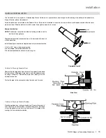
Horizontal Installation
Standard Ceiling Installation
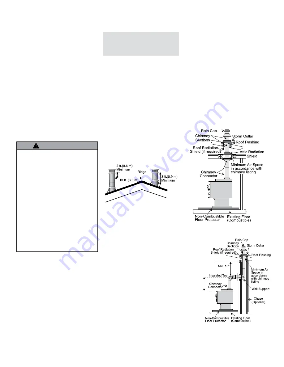
8. If you are using a horizontal connector,
the chimney connector should be as high
as possible while still maintaining the 18"
(457mm) minimum distance from the hori-
zontal connector to the ceiling.
NOTE: Residential Close Clearance and
Alcove installations require a listed
double wall connector from the stove
collar to the ceiling level.
The diagrams below illustrate one way to install
your unit into a standard ceiling or with a horizon-
tal connector. Check with your dealer or installer
for information on other options available to you.
Step-By-Step
Chimney And
Connector
Installation
Note: These are a generic set of chim-
ney installation instructions.
Always follow the manufacturers
own instructions explicitly. Check
the Minimum Recommended Flue
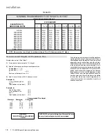
Heights section (Table 1).
1. With your location already established, cut
and frame the roof hole. It is recommended
that no ceiling support member be cut for
chimney and support box installation. If it is
necessary to cut them, the members must
be made structurally sound.
2. Install radiant shield and support from above.
3. Stack the insulated pipe onto your finish
support to a minimum height of 3 feet above
the roof penetration, or 2 feet above any
point within 10 feet measured horizontally.
There must be at least 3 feet of chimney
above the roof level.
Note: Increasing the chimney height
above this minimum level will
sometimes help your unit to
“breathe” better by allowing
a greater draft to be created.
This greater draft can decrease
problems such as, difficult start-
ups, back-smoking when door is
open, and dirty glass. It might be
sufficient to initially try with the
minimum required height, and
then if problems do arise add
additional height at a later date.
4. Slide the roof flashing over your chimney
and seal the flashing to the roof with roofing
compound. Secure the flashing to your roof
with nails or screws.
5. Place the storm collar over the flashing,
sealing the joints with a silicone caulking.
6. Fasten the raincap with spark screens (if
required) to the top of your chimney.
7. To complete your chimney installation, install
the double wall connector pipe from the
stove’s flue collar to the chimney support
device.
This stove may be connected to a lined masonry
chimney or a listed factory built chimney suitable for
use with solid fuels and conforming to ULC629 in
Canada or UL-103HT in the USA. Do not connect
it to a chimney serving another appliance. To do
so will affect the safe operation of both appliances,
and will void the stove warranty. You must comply
with the local authority having jurisdiction and/or
in Canada, CSA installation standard B365-M87.
The chimney connector must be 6" diameter, 24 MSG
Black/Blue steel. Do not use aluminum or galvanized
steel, they cannot properly withstand the extreme
temperatures of a wood fire. The chimney connector
between the stove and the chimney should be as
short and direct as possible.
The chimney connector must be attached to either
an approved masonry chimney or one of the listed
factory built chimneys suitable for use with solid
wood fuel. All joints must be tight and fastened with
sheet metal screws.
WARNING
THE CHIMNEY CONNECTOR IS
TO BE USED ONLY WITHIN THE
ROOM, BETWEEN THE STOVE
AND CEILING/ WALL. NEVER USE
A CHIMNEY CONNECTOR TO PASS
THROUGH AN ATTIC OR ROOF
SPACE, CLOSET OR SIMILAR CON-
CEALED SPACE, OR A FLOOR, OR
CEILING. AN EFFECTIVE VAPOR
BARRIER MUST BE MAINTAINED
AT THE LOCATION WHERE THE
CHIMNEY OR COMPONENT PENE-
TRATES TO THE EXTERIOR OF THE
STRUCTURE. ALWAYS MAINTAIN
THE MINIMUM CLEARANCES TO
COMBUSTIBLES AS REQUIRED
BY THE APPLICABLE BUILDING
CODES.


