36
Chapter 5
VIP SMARTSTART SWITCH
Starting engines using the VIP SmartStart switch
At times there may be a reason to start the vessel from the
engine room where dual VIP SmartStart switches are lo-
cated (one for each engine). The normal helm key switch
system may be inoperative or if maintenance work is be-
ing performed it may just be more practical to start an
engine from engine room switch. The port engine Smart-
Start switch is located at the forward portside engine
room bulkhead. The starboard engine SmartStart switch
is on the starboard side of the forward bulkhead.
Note on the VIP panel the start/stop switch is green.
The
other switch is red and it is for emergency stopping only.
To use the SmartStart switch perfom the following:
1. Make sure the Zeus seacock is in the “open” position.
2. At the helm move the ERC remote control handles to
the neutral position.
3. For each engine to be started, turn the helm ignition
switch to the “on” position.
4. Make sure it is safe to start the engine(s).
5. Find the corresponding SmartStart switch for the en-
gine to be started.
6. Press and release the SmartStart switch for the engine
to be started. The engine starter will automatically begin
to crank and stop once that engine is started.
Stopping engines using the VIP SmartStart switch
For the same reasons mentioned above the operator may
want to stop an engine or engines using the VIP Smart-
Start system located in the engine room.
To stop the engine(s) using the SmartStart switch per-
form the following:
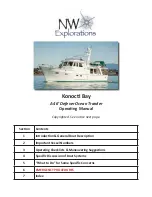
Emergency Stop
(E) Switch
Start/Stop
Switch
System Breaker
Box
VIP
Circuit
Breakers
1. At the helm move the ERC remote control handles to
the neutral position.
2. For each engine to be started,
fi
nd the corresponding
SmartStart switch.
3. Make sure it is safe to shutdown the engine(s).
4. Press and release the “green” start/stop switch for
each engine that you want to stop.
Overcurrent Protection-VIP SmartStart Display
There are system overcurrent breakers located on both
the port and starboard engine SmartStart displays. Note
the breaker sizes and the systems they protect on each
panel as shown in the chart on the following page. Should
a breaker “pop” be sure to locate the source of the prob-
lem before “resetting” the breaker.
A
B
C
Summary of Contents for 53 SC
Page 1: ...52 SC OWNER S MANUAL 53 SC OWNER S MANUAL REGAL 531631 9 2014...
Page 20: ...14 Chapter 1 Notes...
Page 31: ...11 Safety On Board NAVIGATION LIGHT RULES...
Page 42: ...22 Chapter 2 Notes...
Page 51: ...9 Rules Of The Road...
Page 52: ...10 Chapter 3...
Page 81: ...29 Systems MASS COMBI TYPICAL SYSTEM WIRING HOUSE BATTERY...
Page 108: ...56 Chapter 4 TYPICAL AC CIRCUITRY FLOW CHART WITH ISOLATION TRANSFORMER...
Page 181: ...129 Systems...
Page 185: ...133 Systems VHF Key Descriptions...
Page 186: ...134 Chapter 4 VHF Home Screen Description...
Page 187: ...135 Systems VHF Microphone Key Descriptions...
Page 201: ...12 Chapter 5 DIGITAL THROTTLE AND SHIFT DTS HELM CONTROL BOX A B D C E F G H...
Page 206: ...17 Engine Controls JOYSTICK BASIC FUNCTIONS AFT FORWARD SIDEWAYS DIAGONALLY ROTATE...
Page 220: ...31 Engine Controls Courtesy of Cummins...
Page 222: ...33 Engine Controls Courtesy of Cummins...
Page 242: ...53 Engine Controls...
Page 245: ...56 Chapter 5 Notes...
Page 261: ...16 Chapter 6 Notes...
Page 264: ...3 Auxiliary Equipment Operation INTERIOR VIEW MACHINERY COMPONENTS...
Page 287: ...26 Chapter 7 EXTERIOR VIEW MACHINERY COMPONENTS...
Page 314: ...53 Auxiliary Equipment Operation...
Page 324: ...63 Auxiliary Equipment Operation...
Page 325: ...64 Chapter 7...
Page 326: ...65 Auxiliary Equipment Operation SEAKEEPER SPECIFICATIONS...
Page 335: ...74 Chapter 7 SURESHADE SPECIFICATIONS...
Page 341: ...80 Chapter 7...
Page 385: ...39 Cosmetic Care Maintenance...
Page 391: ...45 Cosmetic Care Maintenance TYPICAL DIESEL GENERATOR PARTS DESCRIPTION...
Page 393: ...47 Cosmetic Care Maintenance TYPICAL GENERATOR INFORMATION...
Page 394: ...48 Chapter 8...
Page 399: ...53 Cosmetic Care Maintenance GENERATOR MAINTENANCE RECORD...
Page 410: ...64 Chapter 8 SEAKEEPER STABILIZER SYSTEM CONT...
Page 420: ...74 Chapter 8 WASHER DRYER...
Page 427: ...2 Chapter 9 AIR CONDITIONER DIAGNOSTIC CHART...
Page 428: ...3 Troubleshooting AIR CONDITIONER ELITE CONTROLS...
Page 429: ...4 Chapter 9 AIR CONDITIONER ELITE CONTROLS...
Page 430: ...5 Troubleshooting AIR CONDITIONER ELITE CONTROLS...
Page 431: ...6 Chapter 9 AIR CONDITIONER ELITE CONTROLS...
Page 433: ...8 Chapter 9 MASS COMBI CHARGER DIAGNOSTICS...
Page 434: ...9 Troubleshooting MASS COMBI CHARGER DIAGNOSTICS...
Page 437: ...12 Chapter 9 CABLE CORD REEL...
Page 442: ...17 Troubleshooting ENTERTAINMENT BOSE CINEMATE GS...
Page 443: ...18 Chapter 9 ENTERTAINMENT BOSE CINEMATE GS...
Page 446: ...21 Troubleshooting GALVANIC ISOLATOR...
Page 447: ...22 Chapter 9 GALVANIC ISOLATOR...
Page 448: ...23 Troubleshooting DIESEL GENERATOR Dealer Service Item...
Page 449: ...24 Chapter 9 DIESEL GENERATOR Dealer Service Item...
Page 450: ...25 Troubleshooting DIESEL GENERATOR Dealer Service Item...
Page 451: ...26 Chapter 9 DIESEL GENERATOR Dealer Service Item...
Page 453: ...28 Chapter 9 IPOD...
Page 457: ...32 Chapter 9 REFRIGERATOR ICEMAKER DIAGNOSTICS...
Page 462: ...37 Troubleshooting STEREO FUSION...
Page 463: ...38 Chapter 9 STEREO FUSION CONT...
Page 464: ...39 Troubleshooting STEREO FUSION CONT...
Page 465: ...40 Chapter 9 STEREO FUSION CONT...
Page 468: ...43 Troubleshooting TACHOMETER ELECTRONIC DIESEL...
Page 469: ...44 Chapter 9 TACHOMETER ELECTRONIC DIESEL...
Page 475: ...50 Chapter 9 WASHER DRYER...
Page 476: ...51 Troubleshooting WASHER DRYER...
Page 477: ...52 Chapter 9 WINDLASS...
Page 486: ...9 Storage Winterization WASHER DRYER...
Page 488: ...11 Storage Winterization Notes...
Page 497: ...2 Chapter 12 53 SC STARBOARD PROFILE...
Page 505: ...Technical Information 12 9 53 SC TYPICAL DUAL CHARTPLOTTER WITH AUTO PILOT AND RADAR...
Page 507: ...Technical Information 12 11 53 SC TYPICAL MAIN SHIP S DC ELECTRICAL PANEL REAR VIEW...
Page 509: ...Technical Information 12 13 53 SC TYPICAL BATTERY MANAGEMENT PANEL REAR VIEW...
Page 512: ...Technical Information 12 16 53 SC STARBOARD DASH SWITCH PANEL REAR...
Page 513: ...Technical Information 12 17 53 SC PORT DASH SWITCH PANEL REAR...
Page 514: ...Technical Information 12 18 53 SC DASH ALARM SWITCH PANEL REAR...
Page 515: ...Technical Information 12 19 53 SC CAPTAIN S SEAT SWITCH PANEL REAR...
Page 516: ...Technical Information 12 20 53 SC UPPER COCKPIT SWITCH PANEL...
Page 517: ...Technical Information 12 21 53 SC PORT COCKPIT SWITCH PANEL...
Page 518: ...Technical Information 12 22 53 SC AFT COCKPIT SWITCH PANEL...
Page 519: ...Technical Information 12 23 53 SC OPTIONAL SURE SHADE WIRING DIAGRAM...
Page 520: ...Technical Information 12 24 53 SC OPTIONAL ISO BOOST TYPICAL WIRING DIAGRAM OVERVIEW...
Page 521: ...Technical Information 12 25 53 SC TYPICAL WINDSHIELD WIPER WIRING...
Page 522: ...Technical Information 12 26 53 SC 240 VOLT GFCI WIRING EUROPEAN...
Page 523: ...Technical Information 12 27 53 SC 120 VOLT GFCI WIRING USA...
Page 524: ...Technical Information 12 28 53 SC TYPICAL DC NEGATIVE GROUND WIRING CIRCUIT...
Page 525: ...Technical Information 12 29 53 SC TYPICAL 12 VOLT BATTERY CHARGER SYSTEM DC WIRING...
Page 527: ...Technical Information 12 31 53 SC SEA CHEST FILTRATION SYSTEM 6X6X4 JUNCTION BOX WIRING...
Page 528: ...Technical Information 12 32 53 SC UNDERWATER LIGHT RELAY WIRING...
Page 529: ...Technical Information 12 33 53 SC HALON AUTO FIRE EXTINUISHER SHUTDOWN MODULE WIRING...
Page 530: ...Technical Information 12 34 53 SC TYPICAL MACERATOR INTERLOCK VALVE WIRING...
Page 531: ...Technical Information 12 35 53 SC GARMIN OPTIONAL AIS 600 WIRING CONNECTIONS...
Page 532: ...Technical Information 12 36 53 SC GARMIN OPTIONAL ANCHOR PULL ALARM...
Page 533: ...Technical Information 12 37 53 SC GARMIN 300 WIRING DIAGRAM...
Page 534: ...Technical Information 12 38 53 SC TYPICAL GREY WATER PLUMBING LAYOUT...
Page 535: ...Technical Information 12 39 53 SC TYPICAL BILGE PUMP SEAKEEPER PLUMBING LAYOUT...
Page 536: ...Technical Information 12 40 53 SC TYPICAL AIR CONDITIONER PLUMBING LAYOUT...
Page 537: ...Technical Information 12 41 53 SC PORT PROFILE AND COMPONENT DESCRIPTION...
Page 538: ...Technical Information 12 42 53 SC STARBOARD PROFILE AND COMPONENT DESCRIPTION...
Page 539: ...Technical Information 12 43 53 SC TRANSOM PROFILE AND COMPONENT DESCRIPTION...
Page 542: ...Technical Information 12 46 53 SC TYPICAL OVERALL BOAT DIMENSIONS...
Page 543: ...Technical Information 12 47 53 SC TYPICAL RANGE OF HELM VISIBILITY...
Page 544: ...Technical Information 12 48 53 SC DECK HARDWARE 1...
Page 545: ...Technical Information 12 49 53 SC DECK HARDWARE 2...