background image


Installation and assembly 


Reflex ex separator — 21.11.2016 

English  — 9 


4


Installation and assembly 


CAUTION


Risk of burns 

Escaping hot medium can cause burns. 


Maintain a sufficient distance from the escaping medium. 


Wear suitable personal protective equipment (safety gloves and goggles). 


4.1


Notes 


The following items must be considered when assembling and installing the equipment: 


Do not install the device above sensitive components or close to electrical plant. 


Perform installation in dry and frost-proof locations. 


The flow direction is not pre-determined.  


Ensure a vertical and stress-free installation.  
–   Any stresses that may occur in some cases must be countered by appropriate constructive actions. Stresses may be caused by 

temperature effects, for example. 


Ensure the device is readily accessible in its place of installation. 


Ensure sufficient bearing capability of the installation site. 
–   This applies to filling the separator with water in particular. 
–   If necessary additional structural measures may be required to ensure adequate load 

bearing capacity. 


The device is not a load-bearing structural element.  
–   By default, the calculation of the vessels does not take lateral acceleration forces into 

account. Avoid alternating stresses such as pressure shocks, abrupt pressure changes, or 
strong vibrations. 


Use only approved transport and lifting equipment.  
–   The eyes provided on the device are intended solely as installation aids. 


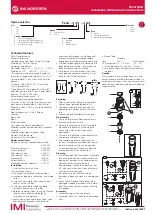
The angle (1) of the lifting tackles must be maximum 60°. 


After attachment of insulation, attach the additional sticker on the outside so that it is readily 
visible. 


Thoroughly rinse the system through after installation of the Reflex Exdirt. 


4.2


Space requirements 


A:  Minimum free space above the top part of the ventilation 


Type: 
82511xx / 82513xx / 82531xx / 82532xx / 82533xx / 82534xx 
50 mm 


Note! 
For connection size DN 450 or greater we recommend 
increasing the minimum space requirement to provide access 
for servicing of the vent. 


B:   Minimum free space below the draw-off tap 


For installation of an Exferro magnetic insert 


For removal of a grid pipe for separators with service flange 


Note! 


You can find a detailed listing of all data at the end of the complete document. 


Welded connection only up to DN 300 


Cooke Industries - Phone: +64 9 579 2185    Email: [email protected]    Web: www.cookeindustries.co.nz

Summary of Contents for Exdirt

Page 1: ...separator 21 11 2016 Exvoid Exvoid HC HiCap Exdirt Exdirt HC HiCap Extwin Extwin HC HiCap GB Operating manual Cooke Industries Phone 64 9 579 2185 Email sales cookeindustries co nz Web www cookeindust...

Page 2: ...Cooke Industries Phone 64 9 579 2185 Email sales cookeindustries co nz Web www cookeindustries co nz...

Page 3: ...7 2 2 Optional equipment 7 2 2 1 Sludge separator 7 2 3 Identification 8 3 Technical data 8 4 Installation and assembly 9 4 1 Notes 9 4 2 Space requirements 9 4 3 Exvoid 10 4 4 Exdirt 10 4 5 Extwin 10...

Page 4: ...ies CAUTION Damage to health The sign in combination with the signal word Caution indicates danger failure to observe the safety information can result in minor reversible injuries ATTENTION Damage to...

Page 5: ...nual and the safety information in particular may cause the destruction and defects of the equipment endanger persons and adversely affect the functioning Any contravention voids the guarantee and lia...

Page 6: ...vices are heavy Consequently there is a risk of physical injury and accidents Use suitable lifting equipment for transportation and installation CAUTION Risk of burns High media and surface temperatur...

Page 7: ...dge particles The device is available in the following variants No Variant 1 Welded connection 2 Flange connection 1 3 Welded connection and service flange 2 3 Flange connection and service flange 2 1...

Page 8: ...cturing Serial no Serial number Art No Article number 3 Technical data Note The following values apply for all standard separators Max temperature 0 110 C Max pressure 10 bar Special versions accordin...

Page 9: ...ice is not a load bearing structural element By default the calculation of the vessels does not take lateral acceleration forces into account Avoid alternating stresses such as pressure shocks abrupt...

Page 10: ...y valve bottom part on the top side of the separator Maintain the large vent freely opened Installation of the Exferro magnetic insert on the bottom side of the separator First insert the Exferro comp...

Page 11: ...eople enter the sphere of influence of magnets The time intervals for maintenance work depend on the specific operating conditions 5 1 Pressure test During a hydraulic pressure test the pressure must...

Page 12: ...diagonally and step by step as per the state of the art 5 2 3 Sludge separator with magnet insert CAUTION Restriction during operation in respect of medical devices due to magnetic field The device co...

Page 13: ...of the product described above with the provisions of the applied Directive s is demonstrated by compliance with the following standards regulations Pressure Equipment Directive AD 2000 according to n...

Page 14: ...Cooke Industries Phone 64 9 579 2185 Email sales cookeindustries co nz Web www cookeindustries co nz...

Page 15: ...1000 2580 671 A 600 DN600 PN16 1530 1630 1200 3020 832 Exvoid HiCap 1 mm m3 h L mm 2 mm H mm HM mm A 60 3 HC 60 3 25 260 132 810 153 A 76 1 HC 76 1 40 260 132 810 163 A 88 9 HC 88 9 54 370 206 965 159...

Page 16: ...6 1530 1630 1200 2960 840 1 mm m3 h L mm 2 mm H mm HM mm D 60 3 R 16 0 60 3 12 5 260 132 521 165 D 76 1 R 23 0 76 1 20 260 132 521 175 D 88 9 R 32 0 88 9 27 370 206 636 170 D 114 3 R 37 0 114 3 47 370...

Page 17: ...600 PN16 3000 1630 1200 3250 840 1 mm m3 h L mm 2 mm H mm HM mm D 60 3 R HC 60 3 25 260 132 706 165 D 76 1 R HC 76 1 40 260 132 706 175 D 88 9 R HC 88 9 54 370 206 861 170 D 114 3 R HC 114 3 94 370 20...

Page 18: ...0 1630 1200 4100 2007 2093 1 mm m3 h L mm 2 mm H mm HM1 mm HM2 mm TW 60 3 R 13 0 60 3 12 5 260 132 785 335 450 TW 76 1 R 13 0 76 1 20 260 132 785 335 450 TW 88 9 R 46 0 88 9 27 370 206 940 413 527 TW...

Page 19: ...16 3000 1630 1200 5800 2857 2943 1 mm m3 h L mm 2 mm H mm HM1 mm HM2 mm TW 60 3 R HC 60 3 25 260 132 1050 468 582 TW 76 1 R HC 76 1 40 260 132 1050 468 582 TW 88 9 R HC 88 9 54 370 206 1285 585 700 TW...

Page 20: ...00 600 700 Exdirt R Exdirt R HC Extwin R Extwin R HC 82522xx 82524xx 82532xx 82534xx mm HiCap mm mm HiCap mm DN 50 DN 65 60 3 76 1 300 570 370 640 DN 80 DN 100 88 9 114 3 400 660 550 900 DN 125 DN 150...

Page 21: ...Cooke Industries Phone 64 9 579 2185 Email sales cookeindustries co nz Web www cookeindustries co nz...

Page 22: ...eflex Winkelmann GmbH Gersteinstra e 19 59227 Ahlen Germany Telephone 49 0 2382 7069 0 Fax 49 0 2382 7069 588 www reflex de Cooke Industries Phone 64 9 579 2185 Email sales cookeindustries co nz Web w...

Reviews: