16
b) Installation
The installation of the receiver depends on the model. For this reason, you should always follow the recommendations
of the model manufacturer regarding receiver installation.
If you want to use the integrated gyro sensor iin the receiver (SVC function of the transmitter will be
enabled), the receiver must be mounted horizontally (max. 10° deviation from the horizontal plane). The
receiver connections must point upwards vertically.
Failure to meet this requirement will result in unpredictable deviations of the control behaviour when using
the gyro sensor.
Independent of this, you should always try to mount the receiver so that it is optimally protected from dust, dirt,
moisture, heat and vibrations. Two-sided adhesive foam (servo tape) or even rubber rings that hold the foam-wrapped
receiver securely in place are suitable for fastening.
Try to place the receiver on the model so that it is not directly next to an electric motor or speed controller.
Warning!
The antenna wire of the receiver has a precisely measured length.
So do not wind up, wrap or cut the aerial wire. This would decrease the range significantly and thus pose a
considerable safety risk.
Guide the antenna wire out of the model through an opening. It is best to use an antenna tube.
For optimal range between the transmitter and the receiver, the transparent end of the antenna wire should
protrude vertically from the model.
Do not place the antenna near metal parts, as this will greatly reduce the range.
c) LED display function
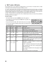
The receiver LED (22) has the following functions:
•
LED off: No voltage/power supply
•
LED solid light: Receiver is ready for operation, transmitter signal is available
•
LED blinks slowly: No transmitter signal (transmitter is switched off or receiver is not paired with transmitter)
•
LED blinks quickly: Pairing process (binding)


