41
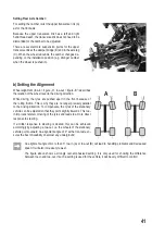
Setting Rear Axle Camber:
For setting the camber, twist the upper transverse link (A)
as for the front axle.
Because the upper transverse link has a left and right
hand thread each, the transverse link does not need to be
dismantled for the camber to be adjusted.
There are several more suspension points for the upper
transverse link at the damper bridge (B) and in the axle leg
(C). When the wheel rebounds, the camber changes de-
pending on the installation position (e.g. stronger camber
when the wheel is pushed in).
b) Setting the Alignment
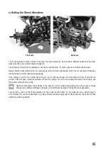
Wheel alignment (toe-in = figure „A“, toe-out = figure „B“) describes
the relation of the wheel level to the driving direction.
While driving, the tyres are pushed apart in the front because of
the rolling friction. This is why they are no longer precisely parallel
to the driving direction. To compensate, the tyres of the stationary
vehicle can be adjusted so that they point slightly inwards. This toe-
in improves lateral cornering of the tyres and leads to a more direct
response to steering.
If a milder response to steering is desired, this can be achieved
accordingly by adjusting a toe-out, i.e. the wheels of the stationary
vehicle point outward. An alignment angle of 0° at the front axle en-
sures the best driveability on almost any underground.
An alignment angle of more than 3° toe-in (A) or toe-out (B) will lead to handling problems and decreased
speed. It will also increase tyre wear.
The figure above shows a strongly over-emphasised setting. It is only used for showing the difference
between toe-in and toe-out. If such a setting is used for the vehicle, it will be very difficult to control!
¦ ¦
A
B
A
B
C


