background image

9

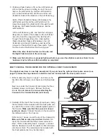
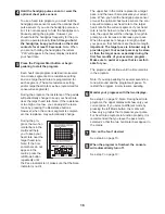
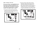
HOW TO INSTALL THE RECEIVER FOR THE OPTIONAL CHEST PULSE SENSOR

The elliptical exerciser is now fully assembled. If you purchase the optional chest pulse sensor (see
page 21), follow the steps below to install the receiver included with the chest pulse sensor.

1. Refer to assembly step 6 on page 7, and remove the

two M4 x 25mm Screws (not shown) and the Bookrack
(7).

Next, look under the Console (8) and locate the three
indicated screws (not shown). Remove the three
screws. Do not remove the screws attaching the
Console to the Console Bracket (not shown).

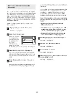
2. Carefully lift the top of the Console (8) as shown. Using

the two small screws included with the chest pulse sen-
sor, attach the receiver to the indicated plastic posts on
the Console. Make sure that the receiver is turned
exactly as shown. 
Connect the wire on the receiver to
the indicated wire on the Console. 

Refer to step 1 above. Lower the top of the Console (8).
Make sure that no wires are pinched. Reattach the
top of the Console with the three screws removed in
step 1. Refer to assembly step 6 on page 7, and reat-
tach the Bookrack (7) with the two M4 x 25mm Screws
(not shown). Note: The remaining wires included with
the chest pulse sensor may be discarded.

Posts

Wire

7

8

8

1

Receiver

2

Screws

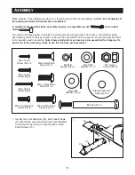
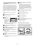
12. Make sure that all parts are properly tightened before you use the elliptical exerciser. Note: Some

hardware may be left over after assembly is completed. 

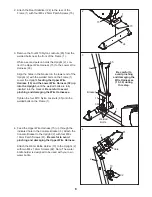
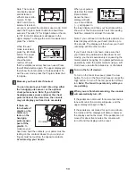
11. Position a Pedal Cushion (74) on the Left Pedal Leg

(28) so that the arrow is pointing to one of the num-
bers on the Left Pedal Leg. Set the Left Pedal Arm
(33) on the Pedal Cushion, with the end of the Left
Pedal Arm inside of the bracket on the Left Pedal Leg.

Hold a Plastic Pedal Arm Spacer (65) between the
Left Pedal Leg (28) and the Left Pedal Arm (33).
Insert the long part of a Bolt Set (67) through the Left
Pedal Leg, the Plastic Pedal Arm Spacer, and the
Left Pedal Arm.

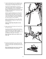
Lift the Left Pedal Leg (28), and hold the Left Upper
Body Arm (5) inside of the bracket on the Left Pedal
Arm (33). Insert the long part of the Bolt Set (67)
through the Left Upper Body Arm. Hold another
Plastic Pedal Arm Spacer (65) between the Left
Pedal Arm and the Left Pedal Leg, and insert the
long part of the Bolt Set through these parts. Tighten
the short part of the Bolt Set into the long part.

Attach the other Pedal Cushion (not shown) and
the Right Pedal Arm (32) in the same way.

65

65

33

32

74

Arrow

28

67

67

5

11

Screws

Summary of Contents for RBEL79020

Page 1: ...ill guarantee complete satisfaction through direct assistance from our factory TO AVOID DELAYS PLEASE CALL DIRECT TO OUR TOLL FREE CUSTOMER HOT LINE The trained technicians on our customer hot line wi...

Page 2: ...OOTING 22 EXERCISE GUIDELINES 23 PART LIST 25 EXPLODED DRAWING 26 ORDERING REPLACEMENT PARTS Back Cover LIMITED WARRANTY Back Cover TABLE OF CONTENTS REEBOK and the Vector Logo are registered trademar...

Page 3: ...the handlebar or the upper body arms when using the elliptical exerciser 10 Keep your back straight when using the ellip tical exerciser do not arch your back 11 If you feel pain or dizziness while ex...

Page 4: ...ou have ques tions after reading this manual please call our Customer Service Department toll free at 1 800 999 3756 Monday through Friday 6 a m until 6 p m Mountain Time excluding holidays To help us...

Page 5: ...o the quantity used in assembly Note Some small parts may have been pre assembled for shipping If a part is not in the parts bag check to see if it has been pre assembled ASSEMBLY M6 x 16mm Button Scr...

Page 6: ...are fully inserted into the bracket Be careful to avoid pinching and damaging the Wire Harnesses Tighten the four M10 Nylon Locknuts 85 onto the welded bolts on the Frame 1 4 Feed the Upper Wire Harn...

Page 7: ...tach the Bookrack to the Console with two M4 x 25mm Screws 96 Be careful to avoid pinching and damaging the wires in the Console 7 96 8 5 6 7 While another person holds the Console 8 near the Console...

Page 8: ...t 2 and center the Pivot Axle Apply a small amount of the included grease to both ends of the Pivot Axle Identify the Left Upper Body Arm 5 which is marked with a decal Insert an Upright Bushing 20 in...

Page 9: ...two M4 x 25mm Screws not shown Note The remaining wires included with the chest pulse sensor may be discarded Posts Wire 7 8 8 1 Receiver 2 Screws 12 Make sure that all parts are properly tightened be...

Page 10: ...lower body hold the handlebar as you exercise HOW TO ADJUST THE PEDAL CUSHIONS The feel of the pedals is affect ed by the posi tions of the pedal cushions The farther back the pedal cush ions are plac...

Page 11: ...Having iFIT com technology is like having a per sonal trainer in your home Using the included audio cable you can connect the elliptical exerciser to your home stereo portable stereo or computer and p...

Page 12: ...nd the track will light one at a time until the entire track is lit The track will then darken and a new lap will begin The upper display The upper display will show the elapsed time the resistance le...

Page 13: ...te contacts Avoid moving your hands When your pulse is detected the Heart Rate indicator above the lower display will light one or two dashes will appear in the lower display and then your heart rate...

Page 14: ...rrent Segment column are lit after the resistance settings have moved to the left the resistance settings will move downward so that only the highest indicators appear in the matrix The program will c...

Page 15: ...ate program 2 is designed to keep your heart rate between 50 and 80 of your maximum heart rate Follow the steps below to use a heart rate program Begin pedaling to activate the console See step 1 on p...

Page 16: ...de button repeatedly until the Pace indicator is lit make sure that the Scan indicator is not lit The upper bar in the matrix represents a target pace and the lower bar represents your actual pace Whe...

Page 17: ...nto a 1 8 Y adapter available at electronics stores Plug the Y adapter into the PHONES jack on your CD player Plug your headphones into the other side of the Y adapter HOW TO CONNECT YOUR PORTABLE STE...

Page 18: ...adapter Plug the Y adapter into the LINE OUT jack on your stereo HOW TO CONNECT YOUR COMPUTER Note If your computer has a 1 8 LINE OUT jack see instruction A If your computer has only a PHONES jack se...

Page 19: ...he adapter into the AUDIO OUT jack on your VCR B Plug one end of the audio cable into the jack beneath the console Plug the other end of the cable into the adapter Plug the adapter into an RCA Y adapt...

Page 20: ...play button is pressed your personal trainer will begin guiding you through your workout Simply follow your personal trainer s instructions The program will function in almost the same way as a person...

Page 21: ...sired links on our Web site to select a program Read and follow the on line instructions for using a program Follow the on line instructions to start the program When you start the program an on scree...

Page 22: ...r best performance regularly tighten both pedals CONSOLE TROUBLESHOOTING If the console displays flicker or darken increase your pedaling pace If the console does not display your heart rate when you...

Page 23: ...ascular sys tem your exercise must be aerobic Aerobic exercise is activity that requires large amounts of oxygen for prolonged periods of time This increases the demand on the heart to pump blood to t...

Page 24: ...s Stretch With one leg in front of the other reach forward and place your hands against a wall Keep your back leg straight and your back foot flat on the floor Bend your front leg lean forward and mov...

Page 25: ...ket 55 2 Eyebolt 56 2 Adjustment Bracket 57 1 Belt 58 1 Reed Switch Bracket 59 1 Reed Switch Clamp 60 1 Reed Switch Wire 61 1 Generator Axle 62 2 Bumper 63 1 Front Stabilizer 64 1 Idler Bolt 65 4 Plas...

Page 26: ...ING MODEL NO RBEL79020 R0303A 2 3 4 5 6 7 8 9 11 9 10 13 14 15 16 17 18 18 19 20 18 16 17 18 18 19 20 18 21 22 22 23 23 23 12 73 73 81 81 93 92 85 94 82 87 87 95 95 82 82 95 95 96 82 82 82 71 82 72 72...

Page 27: ...0 40 41 42 43 43 44 45 46 47 48 49 50 51 51 52 53 54 55 56 57 58 59 60 61 62 62 63 64 65 65 65 65 66 66 67 67 67 67 68 68 69 70 70 71 71 73 73 73 73 73 73 73 73 73 73 75 75 76 76 77 79 79 78 82 82 82...

Page 28: ...abnormal usage or repairs not provided by an ICON authorized service center products used for commer cial or rental purposes or products used as store display models No other warranty beyond that spe...

Reviews: