14
ATTACHING AN ABRASIVE DISC TO THE
SANDING PAD
Note:
The Motor Driven Sanding Pad
located in the swivelling Sanding Head of
the machine, is fitted with a ‘hook and loop’
attachment system.
The ‘loops’ on the back of the abrasive discs
engage with the ‘hooks’ on the surface of
the Sanding Pad.
To attach an abrasive disc:
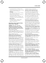
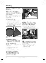
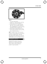
• Ensure that the Sanding Pad is clean and
free from any dirt or debris.
• Press the new abrasive disc onto the
Sanding Pad with the palm of a hand.
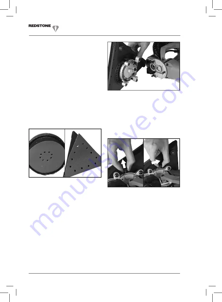
• Ensure that the holes in the new abrasive
disc align with the dust extraction ports in
the Sanding Pad.
(Fig. 8)
To remove an abrasive disc:
• Simply grip the edge of the abrasive disc
and gently peel it from the Sanding Pad.
THE TWO SANDING HEADS
Note:
This machine is provided with two (2)
Sanding Heads:
• A conventional rotating Circular
Sanding Head.
• An oscillating Triangular Sanding Head is
also provided.
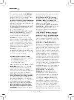
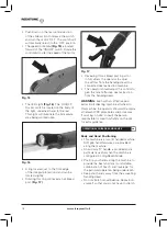
Both are fitted with a quick release
mechanism/coupling and both fit onto
a complimentary coupling built into the
forward motor casing.
(Fig. 9)
To fit a Sanding Head
WARNING:
Only fit or remove a Sanding
Head from this machine with the machine
disconnected from the power supply.
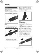
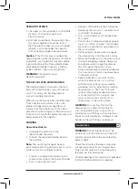
• Pull out the Locking Pin and slide the
Locking Lever
(Fig. 10)
in the quick
release mechanism fully to the left.
Note:
To aid the operator Pictograms are
moulded into the Sanding Head body near
the Locking Lever.
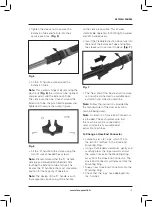
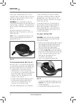
• Offer the Sanding Head up to the
motor coupling ensuring that it is
orientated correctly.
www.leroymerlin.fr
Fig. 9
Fig. 8
Fig. 10


