8
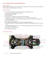
ESC Pads
– ESC power input pads x4
LEDS
– 2 front and 3 rear built in LEDs
LED Switch
– Manual On/Off switch for onboard LEDs
RGB LED Strip
– Rear RGB led connector. Pin definition: ground, +5 (500mA), Data in (connect to RGB signal pin)
DIN&DOUT
– Connect DIN to front RGB strip Din signal. Connect DOUT to front RGB strip Dout signal. Leave
these two pins alone if you don’t have a front RGB Led strip
Front RGB Select
– Connect the two pads with a small blob of solder if you’re not using front RGB Led strip.
Leave the pads unconnected if you have front RGB Led. *The solder bridge is there by default
Video TX
– VTX connector. Filtered and not regulated. Pin definition: ground, power, video
CAM 12V
– FPV cam connector. Filtered and regulated to 12V. Pin definition: ground, +12v, video
CAM 5V
– FPV cam connector. Filtered and regulated by Pololu Step-down. Pin definition: ground, +5v, video
Buzzer Input
– Use a female-female servo cable to connect to Naze32’s negative “-“ buzzer signal pad
Pololu Output
– Power output pins from Pololu
RGB Input
- Use a female-female servo cable to connect to FC’s RGB Data signal pin
RSSI Input
– Use a female-female servo cable to connect to the receiver RSSI signal, pwm and analog compatible.
There’s a built in signal conditioning circuit to convert pwm rssi to analog voltage that MinimOSD can read.
Example: ch-2 on Frsky D4R receiver
MinimOSD Prog. Connector
– Data port to program MinimOSD. Can also be used to retrieve telemetry data from
Naze32. Pin definition: RX, TX, DTR. *Must disconnect when Naze32 is connected to PC


