M
M
o
o
d
d
u
u
l
l
e
e
I
I
n
n
t
t
e
e
g
g
r
r
a
a
t
t
i
i
o
o
n
n
G
G
u
u
i
i
d
d
e
e
V
V
e
e
r
r
s
s
i
i
o
o
n
n
2
2
.
.
1
1
Redpine Signals, Inc. Proprietary and Confidential
Page 15
1.2.4
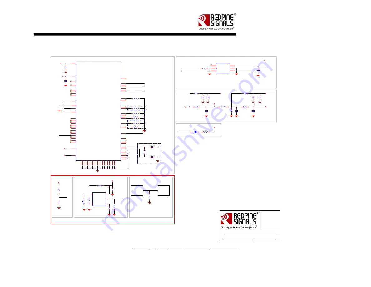
SPI mode Interface Schematic
FB9
BEAD
R25
4.7K
SPI_INTR
SPI_MISO
SPI_MOSI
SPI_CLK
SPI_CS
LED Indication
VDD_EXT
GPIO_16
D1
LED
R8
820E
SPI_INTR
SPI_CS
SPI_CLK
SPI_MOSI
SPI_MISO
VIN_33
NOTE:
R6** v alue should be adjusted based
on driv er output impedance and PCB
Trace Impedance,,(33E is Nominal)
NOTE:
Based on the Host SPI conf iguration, during BOOT UP, SPI Master could be
coming up as GPIO pins.In the wake of this possibility , it may be needed to add a
pull up on the SPI_CS and a pull up (CPOL=1)/pull down(CPOL=0) on the
SPI_CLK. The v alue of pull up/ pull down resistor should f ollow the
recommendations as giv en on the HOST side.
J2
SPI Interface Connector
CD/DAT3
1
CMD
2
VSS1
3
VDD
4
CLK
5
VSS2
6
DAT0
7
DAT1
8
DAT2
9
R6**
C10
10uF(0805)
RESET_N
R10
100K
C13
0.1uF
OPTION-1
RESET_N
C14
8.2nF
R9
1M
R12
100K
U2
MAX6415
VCC
5
SRT
4
RESETn
1
GND
2
RESET IN
3
OPTION-2
R
11
1M
C12
0.1uF
SW
1
1
2
RESET Circuitry
VDD_EXT
VDD_EXT
Redpine Signals Confidential
H os t M C U may direc tly drive the RE SE T _N
pin of the module as s hown below.
OPTION-3
Note: Ensure a reset assertion time of 20ms.
HOST MCU
RESET_N
MCU pin
driving
RESET_N
R13
10K
VIN_33
GPIO_16
R23
4.7K(NP)
R24
4.7K(NP)
R22
4.7K(NP)
RESET_N
C4
10uF(0805)
R26
1K
R27
1K
R28
1K
C3
2.2uF
U1
RS9113 based Module
HOST_SEL_0
36
VIN_MOD
33
GPIO_21
31
GPIO_16
25
GPIO_15
24
USB_VDDP
21
GPIO_18
30
GPIO_17
28
SDIO_DATA2
16
SDIO_CLK
18
SDIO_DATA3
15
SDIO_DATA1
14
SDIO_CMD
17
SDIO_DATA0
13
USB_VDDS
22
USB_VBUS
9
USB_DP
11
USB_ID
12
HOST_SEL_1
35
WURX
1
GPIO_19
32
GPIO_11
7
GPIO_12
41
VRF33
34
GPIO_10
5
GPIO_14
8
GPIO_9
6
GPIO_13
49
XTAL_32Khz_N
4
XTAL_32Khz_P
3
VBATT
52
ULP_ANAGPI
50
RESET_N
51
USB_VDDD
42
JP1
48
JP0
47
BOOTLOAD_EN
27
USB_DN
10
SDIO_VDD_18_33
19
GPIO_8
29
VOUTLDOP3
40
USB_VDDA
43
HOST_BB_EN
39
ULP_GPIO_0
2
AUX_DAC_OUT
38
JP2
45
JNC
46
BOOT_MODE_0
20
AUX_ADC_IN0
44
GPIO_7
23
VOUTLDOP1
37
GPIO_2
26
GN
D
53
GN
D
54
GN
D
55
GN
D
56
GN
D
57
GN
D
58
GN
D
59
GN
D
60
GN
D
61
GN
D
62
GN
D
63
GN
D
64
GN
D
65
GN
D
66
GN
D
67
GN
D
68
GN
D
69
GN
D
70
GN
D
71
GN
D
72
GN
D
73
GN
D
74
GND
75
GND
76
GND
77
GND
78
GND
79
with integrated antenna
VINMOD
VRF33
DVDD33
C15
0.1uF
FB8
BEAD
VDD_EXT
VIN_33
C9
0.1uF
DVDD33
C8
47uF(CASE B)
FB6
BEAD
FB7
BEAD
VRF33
C17
10uF(0805)
C18
22uF(CASE B)
Tantalum
C20
0.1uF
L1
4.7uH
C19
0.1uF
C21
1uF
Power Supply Filter Section
VINMOD
Note:
R22 should be mounted w hen ULP not USED
Y 1
MC-146
1
4
C11
20pF
C24
20pF
NO POPULATE
Note:
Y1 is used for accurate w akeup time
Note:
R24 should be mounted for USB Enumeration
R24 should not be mounted for USB_CDC Enumeration
Title
Size
Document Number
Rev
Date:
Sheet
of
RS9113 based Module with integrated antenna -SPI
1
1
Rev0.0
Figure 4: SPI mode Interface Schematic


