background image

18

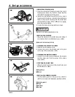
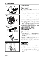
STARTING ENGINE

The cutting head will start rotating upon the
engine starts.

1. Rest the unit on a flat, firm place. Keep the

cutting head off the ground and clear of
surrounding objects as it will start rotating upon
starting of the engine.

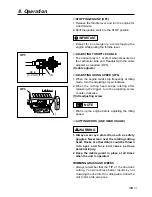
2. Push the primer pump several times until

overflown fuel flows out in the clear tube. (OP1)

3. Move the choke lever to the closed position.

(OP2)

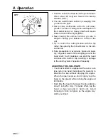
4. Set the ignition switch to the “start” position.

While pulling the throttle lever, push the set
button, and release the throttle, then the throttle
lever is in to the “start” position. (OP3)

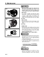
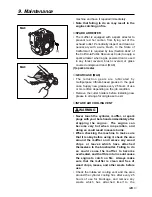
5. While holding the unit firmly, pull out the starter

rope quickly until engine fires. (OP4)

(1) choke lever  (2) close  (3) open
(4) ignition switch  (5) start  (6) stop
(7) throttle set button

• Avoid pulling the rope to its end or returning it by

releasing the knob. Such actions can cause
starter failures.

6. Move the choke lever downward to open the

choke. And restart engine. (OP2)

7. Allow the engine to warm up for a several

minutes before starting operation.

1. When restarting the engine immediately after

stopping it, leave the choke open.

2. Overchoking can make the engine hard to start

due to excess fuel. When the engine failed to
start after several attempts, open the choke and
repeat pulling the rope, or remove the spark plug
and dry it.

NOTE

IMPORTANT

WARNING

8. Operation

OP1

(1)

(2)

(3)

OP2

(4)

(7)

(5)

(6)

(4)

(7)

(5)

(6)

BCZ2500S
BCZ2500SU

BCZ2500SW

OP3

OP4

Summary of Contents for BCZ2500S

Page 1: ...defects or other reproductive harm WARNING Before using our brushcutters please read this manual carefully to understand the proper use of your unit WARNING BCZ2500S DRIVE UNIT 900101 and up ENGINE UN...

Page 2: ......

Page 3: ...e followed in order to prevent accidents which could lead to serious bodily injury or death This mark indicates instructions which must be followed or it leads to mechanical failure breakdown or damag...

Page 4: ...fl oz 0 65 Transmission Centrifugal clutch Rigid driveshaft Reduction ratio 1 357 Cutting head rotating direction Counter clockwise Operator view Durability period 300hrs Standard Accessories 4 in 2...

Page 5: ...ng label peel off or become soiled and impossible to read you should contact the dealer from which you purchased the product to order new labels and affix them in the required location s Never modify...

Page 6: ...1 CALIFORNIA EMISSION REGULATIONS FOR SI SORE s COMPLIANCE PERIOD CATEGORYA ENGINE FAMILY 1KZXS 0254QR EM ENGINE DISPLACEMENT 25 4cc REFER TO OWNER S MANUAL FOR MAINTE NANCE SPECIFICATIONS AND ADJUSTM...

Page 7: ...ou should wear proper clothing and protective equipment 1 Helmet 2 Ear protectors 3 Protection goggles or face protector 4 Thick work gloves 5 Non slip sole work boots 2 And you should carry with you...

Page 8: ...te the product properly and in a safe manner 2 When planning your work schedule allow plenty of time to rest Limit the amount of time over which the product is to be used continuously to somewhere aro...

Page 9: ...ers and fuel leakage Make sure that the cutting attachment is properly installed and securely fastened 4 Be sure the debris guard is firmly attached in place 5 Always use the shoulder strap Adjust the...

Page 10: ...art than the width of your shoulders so that your weight is distributed evenly across both legs and always be sure to maintain a steady even posture while working 2 Keep cutting attachment below waist...

Page 11: ...her part or when replacing the oil or any lubricant always be sure to use only RedMax products or products which have been certified by RedMax for use with the RedMax product 4 In the event that any p...

Page 12: ...re nearby before refueling 4 Wipe spilled fuel completely using a dry rag if any fuel spillage occurs during refueling 5 After refueling screw the fuel cap back tightly onto the fuel tank and then car...

Page 13: ...crews gradually by turns CONNECTING THROTTLE WIRE 1 Remove the air cleaner cover 2 Connect the end of the throttle wire to the joint on the top of the carburetor SE2 CONNECTING SWITCH WIRES Connect th...

Page 14: ...G HANDLE Mount the handle to the shaft tube and clamp it at a location that is comfortable to you SE6 1 About 14 5 inches 37cm CONNECTING THROTTLE WIRE 1 Remove the air cleaner cover 2 Connect the end...

Page 15: ...the gear box loosen and remove the hexagon nut left handed 2 Fit the holder attached to the upper holder Then screw in the cutting head to the gear shaft over the holders Hand tighten it securely BAL...

Page 16: ...thout addition of any major hardware or the introduction of an inert material during combustion These engines are certified to operate on unleaded gasoline Make sure to use gasoline with a minimum oct...

Page 17: ...fueling point before starting the engine 3 Stop the engine before refueling the unit FOR YOUR ENGINE LIFE AVOID 1 FUEL WITH NO OIL RAW GASOLINE It will cause severe damage to the internal engine part...

Page 18: ...mly pull out the starter rope quickly until engine fires OP4 1 choke lever 2 close 3 open 4 ignition switch 5 start 6 stop 7 throttle set button Avoid pulling the rope to its end or returning it by re...

Page 19: ...the cutting head keeps rotating after releasing the trigger turn the adjusting screw counter clockwise 1 idle adjusting screw Warm up the engine before adjusting the idling speed CUTTING WORK LINE HE...

Page 20: ...load on the arm and hands 6 Take precautions to avoid wire grass and dead dry long stem weeds from wrapping around the head shaft Such materials can stall the head and cause the clutch to slip resulti...

Page 21: ...ng and the washers are in place MA4 6 While holding the spool against the housing pull the line ends to release them from the slot 7 Line up the slot on the bottom cap with the hook on the housing pre...

Page 22: ...re and mis firing are often caused by a fouled spark plug Clean the spark plug and check that the plug gap is in the correct range For a replacement plug use the correct type specified by RedMax MA7 R...

Page 23: ...Remove the cutter holders before installing new grease to arrange for old grease to exit INTAKE AIR COOLING VENT Never touch the cylinder muffler or spark plugs with your bare hands immediately after...

Page 24: ...on the part of the brushcutter MA10 1 cylinder 2 intake air cooling vent back PROCEDURES TO BE PERFORMED AFTER EVERY 100 HOURS OF USE 1 Remove the muffler insert a screwdriver into the vent and wipe...

Page 25: ...causes of engine starting failure Before storing the unit empty the fuel tank and run the engine until it uses all the fuel left in the fuel line and the carburetor Store the unit indoor taking neces...

Page 26: ...t to be cut OPT1 When replacing blade always be sure to use products which have been certified by RedMax When sharpening removing or reattaching the blade be sure to wear thick sturdy gloves and use o...

Page 27: ...ipped with a centrifugal clutch mechanism so the cutting attachment begins to rotate as soon as the engine is started by putting the throttle into the start position When starting the engine place the...

Page 28: ...lade and the holder have been fastened according to instruction and the blade turns smoothly without abnormal noise OPT7 The rotating parts fastened incorrectly may cause serious accident to the opera...

Page 29: ...t the blade contact materials it cannot cut such as hard woody vines and brush or rocks fences metal etc c Be extra prepared for bounce if you must cut where you cannot see the blade making contact su...

Page 30: ...a grinder It is recommended that filing should be done by professionals Especially regarding filing the saw blade Leave it to the professionals TRANSPORTING THE UNIT When you finish cutting in one loc...

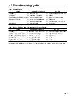
Page 31: ...GAP 0 6 0 7mm spark plug disconnected retighten Case 2 Engine starts but does not keep running Hard re starting CHECK PROBABLE CAUSES ACTION fuel tank incorrect fuel or staled fuel drain it and with c...

Page 32: ...32...

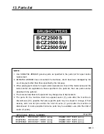
Page 33: ...described in the parts list may change due to improvement 5 The parts for the machine shall be supplied seven 7 years after the machine is discontinued It is possible that some specific parts may be s...

Page 34: ...13 Parts list 34 Fig 1 DRIVE UNIT BCZ2500S S N 900101 and up BCZ2500SU S N 000000 and up...

Page 35: ...LEVER COMP T3002 12202 1 24 LEVER 6110 14412 1 25 COVER COMP 6110 14410020 1 26 SHAFT 6110 14410060 1 27 BUTTON 6110 14410090 1 28 SPRING 6110 14410080 1 29 CORD A T3002 12220 1 30 CORD B T3002 12230...

Page 36: ...13 Parts list 36 Fig 2 DRIVE UNIT BCZ2500SW S N 100001 and up...

Page 37: ...COMP T3002 95400 1 33 LEVER ASSY 6234 14601 1 34 COVER COMP 6234 14601020 1 35 SHAFT 6110 14410060 1 36 BUTTON 6110 14410090 1 37 SPRING 6110 14410080 1 38 CORD A BLACK T3002 95710 1 39 CORD B RED T3...

Page 38: ...Fig 3 ENGINE UNIT BCZ2500S S N 35208 and up BCZ2500SU S N 35208 and up BCZ2500SW S N 35208 and up 38 13 Parts list...

Page 39: ...1918 81170 1 74 SCREW 1850 81530 4 75 WASHER 5500 81160 1 76 SCREW M5x60 0263 90560 2 77 MUFFLER ASS Y 4810 15100 1 78 MUFFLER 4810 15111 1 79 ARRESTER 4810 15140 1 80 BOLT M5x50 01252 30550 2 81 GAS...

Page 40: ...sibilities As the small off road engine owner you are responsible for the performance of the required maintenance listed in your owner s manual KOMATSU ZENOAH recommends that you retain all receipts c...

Page 41: ...ALENT IN PERFORMANCE AND DULABILITY MAY BE USED IN NON WARRANTY MAINTENANCE OR REPAIRS AND SHALL NOT REDUCE THE WARRANTY OBLIGATION OF THE COMPANY THE COMPANY IS LIABLE FOR DAMAGES TO OTHER ENGINE COM...

Page 42: ...en durabilit peut tre utilis e pour l entretien hors garantie ou les r parations hors garantie et ce sans r duire l obligation de garantie incombant la soci t La soci t sera tenue responsable des domm...

Reviews: