Red
MAX
™
Subscriber Modem
User Manual
70-00057-01-01-DRAFT
Proprietary Redline Communications © 2006
December
13,
2006
Page 20 of 60
3.2 LED
Indicators
The subscriber features LED indicators to assist with installation and
troubleshooting of the wireless interface and the Ethernet interface.
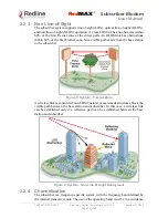
Figure 8: Subscriber LED Display
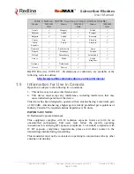
3.2.1 WiMAX / WAN Signal
The subscriber features five LEDs to indicate signal strength. If no signal or a
weak signal is detected, only the left LED (-) will be lit. As signal strength
increases, more LEDs will be lit. A strong signal is indicated by all LEDs being
lit.
Table 3
:
System - Indoor CPE WAN LEDs
Phase Activity
Description
1 Power-on
/
Reset
All LEDs are on for a short period.
2 Frequency
Scanning
Walking LED on (left to right to left).
3 Network
Entry
The number of LEDs blinking represent the received
signal strength. Value is from zero (all LEDs off) to
five (all LEDs on). See table following.
4 Subscriber
is
Registered
The number of LEDs on represent the received signal
strength. Value is from zero (all LEDs off) to five (all
LEDs on). See table following.
Table 4
:
System - Indoor CPE WAN LEDs - Signal Strength
LED Indicators Lit
Signal Strength (RSSI)
5 <
-45
4
-45 to -58.9
3
-58 to -75.3
2
-75 to -86.5
3.2.2 LAN
System
The LAN LEDs indicate connectivity and activity on the Ethernet port. Refer to
the following table for details.
Table 5
:
System - LAN LEDs
Left LED
LED is on when the Ethernet port connection is active.
Right LED
LED blinks when there is Ethernet data traffic.

