


Redback® Proudly Made In Australia
7
Redback®
Programmable Control System
2.4 A 6515 TWO RELAY DISTRIBUTION BOX (HIGH CURRENT) CONNECTION GUIDE
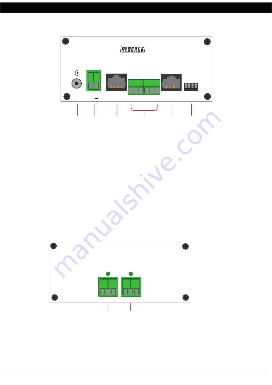
Fig 2.4a shows the layout of the front of the A 6515 Relay Distribution Box.
Fig 2.4a
1
24V DC input
Connects to a 24V DC Plugpack with a 2.1mm Jack (Please observe the polarity, centre positive).
2
24V DC Input
Connects to a 24V DC source via a euro block (Please observe the polarity).
3
RJ45 interface
This RJ45 port is for connection to other Redback
®
compatible devices.
4
Serial Input
This input takes either an RS232 or RS485 signal. This can be connected to one of the serial outputs of the
A 6505 or to a third party system. Follow standard RS232 or RS485 wiring when connecting these terminals.
5
RJ45 interface
This RJ45 port is for connection to the A 6500 wall plate.
6
DIP Switches
1 ON: Accept serial codes through RS485 input.
2 ON: Accept serial codes through RS232 input.
3 ON: Accept serial codes from wall plate.
4: Not Used
NOTE: Only one of the DIP switches 1-3 can be on at any time.
Fig 2.4b shows the layout of the rear of the A 6515 Relay Distribution Box.
Fig 2.4b
1
Output 1
This output provides a voltage free output with a normally open and normally closed contact. This is configured via
the software as the relay 13 output. (The maximum current rating of these contacts is 16A.) The LED above the
terminals illuminate while the output is active.
2
Output 2
This output provides a voltage free output with a normally open and normally closed contact. This is configured via
the software as the relay 14 output. (The maximum current rating of these contacts is 16A.) The LED above the
terminals illuminate while the output is active.
A 6515 Distribution Box
+ _
+
-
DIP
Switches
To Wall
Plate
24V DC
IN
24V DC IN
1
2
3
4
RS485
Serial
GND
B
A
GND
TX
RX
To Other
Devices
1 2 3 4
1 2
3
4
5
6
1
2
GND
N/C
N/O
GND
N/C
N/O
Out 1
Out 2
Connection Guide