background image

33

USER GUIDE

Bluetooth

®

 Pairing Instructions

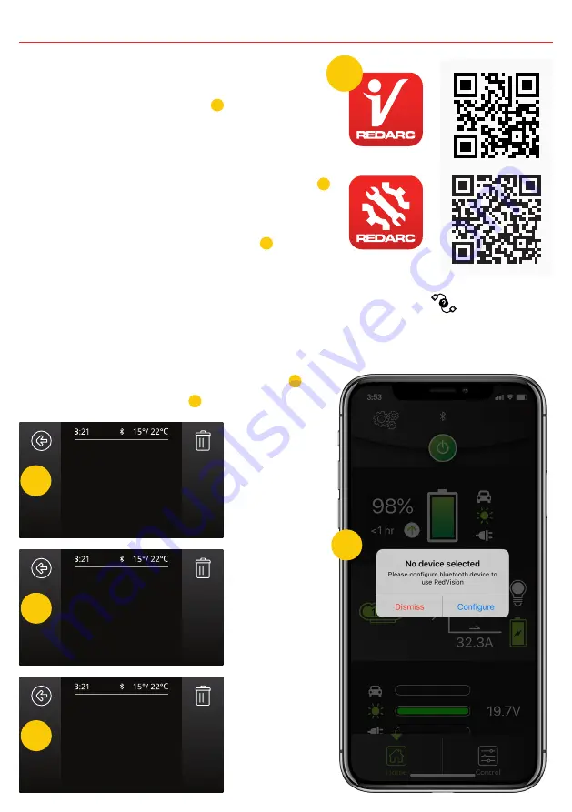
1.  Install the RedVision or Configurator App (scan 

the corresponding QR code 

1

 or search for 

“REDARC” on your device’s app store)

2.  On the Display, press Left, navigate to display 

settings & press the Bluetooth

®

 Soft Key – this 

should say “Your display is ready for pairing” 

2

3.  Open the RedVision or Configurator App
4.  On the RedVision App, if you get a “No device 

selected” pop-up, click “Configure” 

3

. If using 

the Configurator App, move to step 5.

5.  Choose your Display from the list (this should match the serial number on your 

Display, which can be found in R-Bus Diagnostics on the display       )

6.  Read and agree to any disclaimers shown.
7.  Wait for passcode prompt (this may pop up or show up as a notification depending 

on your phone)

8.  Enter the 6-digit code shown on Display 

4

9.  “Your device is paired.” 

5

Bluetooth Pairing

Active

Passcode: 956825

Enter the passcode

above into your device.

BT FW: 3.0.1.1

Bluetooth Pairing

Advertising

Your display is ready for

pairing.

BT FW: 3.0.1.1

Bluetooth Pairing

Successful

Your device is paired.

BT FW: 3.0.1.1

2

3

4

5

1

RedVision

Configurator

Summary of Contents for MANAGER 30

Page 1: ...Battery Management System BMS1230S3R THE MANAGER ...

Page 2: ... is damaged it must be replaced by a special cord or assembly available from the manufacturer or service agent 5 Cable and fuse sizes are specified by various codes and standards which depend on the type of vehicle the Battery Charger is installed into Selecting the wrong cable or fuse size could result in harm to the installer or user and or damage to the Battery Charger or other equipment instal...

Page 3: ...by in case battery acid contacts skin clothing or eyes c Wear complete eye protection and clothing protection Avoid touching eyes while working near a battery d If battery acid contacts your skin or clothing remove the affected clothing and wash the affected area of your skin immediately with soap and water If battery acid enters your eye immediately flood the eye with running cold water for at le...

Page 4: ...ions 11 1 Mounting the Main Unit 12 2 Mounting the Display 13 3 Mounting the Battery Sensor 16 3 DC Cable Size Requirements 16 4 The Manager30 Wiring Connections 18 1 Load Disconnect Feature 18 2 Ignition Trigger Feature 18 3 Connecting the Battery Sensor 19 4 Wiring the Main Unit 19 5 Batteries 21 6 MPPT Solar Regulator 22 3 USER Guide 23 1 The Display 23 2 Basic Screens 25 3 Display Settings 27 ...

Page 5: ...al to or below the output voltage 6 State of Charge SOC indication means you will always know how fully charged the battery is and how much longer it will need to achieve full charge An easy to operate high quality user friendly graphical display module lets you know what s going on at all times 7 The Manager30 is very reliable and includes reverse polarity protection without depending on fuses an...

Page 6: ...essed into the dashboard of an RV for example The Display also allows a Bluetooth connection to your Smartphone via the RedVision App which provides the same data and control available on the Display all in the palm of your hand 1 3 The Kit Includes 5 Main Unit Battery Sensor Display Output Connector 5m CANBus Cable Power Cable 1 2 3 4 5 6 2009 19 EC adapting to Council Directive 72 245 EEC relati...

Page 7: ...Short Circuit Protection Yes Surge Protection Yes Reverse Polarity Protection Yes Overload Protection Yes Max Volts Battery Terminals 25 C Nominal Storage Mode Touring Mode Float Gel Setting 14 4V 14 4V 13 5V AGM Setting 14 4V 14 4V 13 5V Calcium Setting 16 0V 15 2V 13 5V Standard Lead Acid Setting 15 5V 14 8V 13 5V Lithium Setting 14 5V 14 5V 13 6V Thermal Specifications Operating Temperature 40 ...

Page 8: ...7 1 INTRODUCTION 107 5 18 5 11 7 178 6 156 158 19 15 25 5 39 Ø 4 5 m m X 4 91 6 96 103 11 Optional Spacer 185 429 445 404 82 79 Figure 1 4 1 Main Unit Dimensions Figure 1 4 2 Display Dimensions ...

Page 9: ...e the house battery is monitored to detect only a limited number of faults such as short circuit over current and over voltage This allows The Manager30 to operate correctly even when loads are connected to the house battery This mode will always produce an output unless a fault condition is detected and will cycle through the three stages as required to maintain the house battery as outlined in F...

Page 10: ...o ensure the battery stays charged Maintenance stage turns The Manager30 output off but continues to monitor the House Battery and will revert to Float stage when the House Battery drops below 12 7V 12 8V for Lithium for 5 seconds or below 90 SoC for 1 hour NOTE If The Manager30 is set to Storage mode and the vehicle is started The Manager30 will automatically switch to Touring mode once it senses...

Page 11: ...cted to the user setting Any excess BMS1230S3 capacity is available to power loads running from the battery under charge If no loads are running from the battery total current fromThe Manager30 will be restricted to the level set by the user 1 7 Recommended batteries Because of the rapidly changing nature of batteries and battery technology REDARC avoid recommending specific battery makes or model...

Page 12: ...ajor components of The Manager30 the Main Unit the Display and the Battery Sensor Vehicle Battery Not Supplied House Battery Not Supplied BMS1230S3 Solar Panels Not Supplied Display To Loads Not Supplied Battery Sensor 240VAC Mains Power DC DC Power Source Figure 2 1 1 System Layout Figure 2 2 1 The Manager30 System ...

Page 13: ...ble to the house battery The cable length should be less than 2m The Main Unit must be mounted to a flat solid support using M6 sized screws or bolts using all four mounting holes The Main Unit must be fixed using suitable screw mounts Failure to adequately mount the unit such as using adhesives to mount the unit will result in unreliable operation of the charger REDARC recommends that the Main Un...

Page 14: ...ironments such as being exposed to rain or severe amounts of dust or full time direct sunlight Ensure that the Display is not mounted in vehicle head impact zones Doing so may result in injury to the driver and or passenger in the event of an accident Ensure the Display is not mounted where it may distract the driver of the vehicle Distracting the driver may result in an accident Spacer optional B...

Page 15: ...2 INSTALLATION GUIDE Removing the Display Fascia 14 ...

Page 16: ...cutout template Flush Mount Drill Cut Dimensions Surface Mount Drill Cut Dimensions 91 156 164 101 109 132 58 35 45 91 156 Ø45mm 24 46 NOT TO SCALE Refer to page 37 for a 1 1 cutout template NOT TO SCALE Refer to page 37 for a 1 1 cutout template 15 ...

Page 17: ...n the type of vehicle the Battery Charger is installed into Selecting the wrong cable or fuse size could result in harm to the installer or user and or damage to The Manager30 or other equipment installed in the system The installer is responsible for ensuring that the correct cable and fuse sizes are used when installing the Battery Charger The Manager30 is capable of drawing up to 50A from the V...

Page 18: ...utput wire be of the size outlined in Table 2 3 2 1 For longer runs using 10mm is recommended however this will lower efficiency by up to 3 the recommended maximum length is 5m Distance metres from The Manager30 to House battery Recommended Cross Sectional Area mm Recommended Diameter Equivalent 1 5m 8 8 B S 1 5m 10 6 B S Figure 2 3 2 1 Recommended output cable size 17 Figure 2 3 1 1 Recommended i...

Page 19: ...Output Connector plug the connector into the Main Unit When disconnecting remove the Output Connector from the Main Unit first The DC Input should be disconnected next followed by the Ground chassis connection then the Battery Output connection 2 4 1 Load Disconnect Feature The Load Disconnect wire is a ground switch to activate a relay for disconnection of any loads running from the house battery...

Page 20: ...ing the provided nut ensure the head of the bolt is also held by a spanner to prevent twisting and damage to the shunt Do not over tighten Figure 2 4 3 1 Battery Sensor connections to Vehicle Common Ground to House Battery Positive Terminal to House Battery Negative Terminal to CANBus Interface CAN Bus Connection 2 4 4 Wiring the Main Unit Refer to Figure 2 4 4 1 for required connections and to Fi...

Page 21: ...Not supplied Load Fuses Not supplied 1 Ignition Trigger SBI12 BLD 1 The size of this fuse relates to the total current draw of all the loads connected to the House Battery and should be rated slightly higher than this REDARC recommend the use of MIDI Style Fuses 2 Essential loads are loads which must be left on at all times until the battery is flat Non essential loads are those switched off when ...

Page 22: ...Figure2 5 1and2 5 2showstandardwiringforbatteriesinseriesandparallelrespectively 12V 12V 12V Ground To 12V system Battery Sensor Figure 2 5 1 Batteries in Series Figure 2 5 2 Batteries in Parallel Ground 6V To 12V system Battery Sensor 6V To ensure that all batteries are equally charged loads and The Manager30 should be connected with ground and 12V power connected diagonally opposite across all b...

Page 23: ...ions change the MPPT algorithm adjusts its parameters accordingly in order to maintain the optimum point at which the solar panels can deliver the most power An array of solar panels can be connected to The Manager30 solar input on the condition that the open circuit output voltage of the array is at least 17 5V and does not exceed 32V For this reason 12V panels must be connected in parallel Refer...

Page 24: ...ge status estimated charge time and State of Charge SOC per hour over a day and per day over a month It also allows you to select charging profiles specific to the battery type and size It also provides the Bluetooth interface for the RedVision App With a RedVision Distribution Box connected the Display allows control of an Inverter and up to 10 outputs along with information from 2x temperature a...

Page 25: ...er Button ONCE will open a Power Button instruction dialogue and allow switching between Storage and Touring modes Pushing the Power Button TWICE will invoke the Master Switch function when a Distribution Box is installed This function switches a defined set of devices and can be customised by the installer to user specifications HOLDING the Power Button will put the screen into Standby mode Pushing...

Page 26: ...d selected by Soft Key Pushing the Up Down arrows cycle through the available settings menus Pushing the top left Back Soft Key will return the user back to the Home Screen Changing Settings Once the desired Settings Screen is selected using the Soft Keys the available settings can be modified Pushing the Up Down arrows will cycle through the settings Pushing the Left Right arrows will modify the ...

Page 27: ... either the SoC on the hour for the previous 24 hours State of Charge per Hour or the maximum and minimum SoC each day for the previous 30 days Pushing the Left and Right buttons at this screen will cycle through the logs displaying the information at the top of the graph State of Charge per Day 19 Jul 93 96 Solar Energy per Day 19 Jul 150Wh Solar Power input log The Solar Power input log keeps tr...

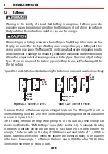
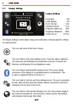
Page 28: ...en allows connection of the Display to a standalone device via Bluetooth This process is explained further in Section 3 7 This icon links to the Date and Time settings screen The user is prompted to enter date and time upon first startup however should this need to be changed it can be done in this menu This icon links to the Regional Settings menu This menu allows toggle of the Clock format betwe...

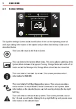
Page 29: ...e Mode will switch off all loads and set the Manager into Storage Mode should one be connected This icon links to the About Us screen This screen provides contact information for REDARC This icon links to the RBus Diagnostics screen This screen provides a serial number for each REDARC device connected to the system More information on the selected device can be found by clicking the top right Soft...

Page 30: ...ion of the Manager product so it is important to ensure this is correct This icon links to the Charger Settings screen This screen allows setting of the DC input trigger on the Manager and allows modification of the Low Voltage and SoC alarm levels This icon links to the BMS Load Disconnect screen This allows for setting of the Load Disconnect feature on the Manager NOTE This feature operates simi...

Page 31: ...val of the fault condition If The Manager30 detects a problem with the charging system that does not prevent it from charging the battery it will alert you via a Warning screen and an alarm buzzer and continue charging The screen will give a brief description of the problem and allow you to select either Clear or Ignore Both options will clear the warning screen After selecting Clear however The M...

Page 32: ...r DC supply over voltage The DC input voltage is too high over 32V Check DC input refer to specified input range Solar supply over voltage The solar input voltage is too high above 32V Check solar input refer to specified input range No battery sensor connected The supplied battery sensor is not connected or is faulty Connect battery sensor if faulty return to supplier Battery SoC low Disconnect a...

Page 33: ...r smartphone for example turning lights inverter water pumps and other loads such as televisions electric steps and fridges on or off It also provides the user with the ability to monitor water levels temperature The RedVision App replicates MOST of the display and switching features of the Display The RedVision App and its interactions with the Manager30 System have not been tested on all smartph...

Page 34: ...gurator App move to step 5 5 Choose your Display from the list this should match the serial number on your Display which can be found in R Bus Diagnostics on the display 6 Read and agree to any disclaimers shown 7 Wait for passcode prompt this may pop up or show up as a notification depending on your phone 8 Enter the 6 digit code shown on Display 4 9 Your device is paired 5 Bluetooth Pairing Acti...

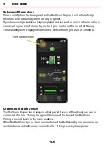
Page 35: ... top left of the app The available paired Displays will be shown Select the one you want to connect to Three Gear Symbol Connecting Multiple Devices The RedVision Display can manage multiple paired devices although only one can be connected at a time Closing the app will disconnect the device from RedVision Pairing a second device is the same as above When the RedVision App is closed on one device...

Page 36: ... A partially shaded panel or low light conditions such as dawn or dusk will increase the target solar panel voltage level to match the maximum power point In this situation solar will be selected as a source however little or no current will be flowing into the battery 2 hrs 30 9A 30 9A 0A 75W 150Wh V 19 2V V Q I have just finished wiring The Manager30 and when I turn the unit on the Display says ...

Page 37: ...4 DISPLAY DRILL CUTOUT TEMPLATE TOP Without Spacer W i t h S p a c e r 36 ...

Page 38: ...37 ...

Page 39: ...ontrol of Redarc 7 Warranty claims in respect of a Product must be made in writing to Redarc at the postal address or email address specified in clause 21 within the Warranty Period Such claims must include the following 7 1 details of the alleged defect or fault and the circumstances surrounding the defect or fault 7 2 evidence of the claim including photographs of the Product where the subject o...

Page 40: ...om United States 1 704 247 5150 Canada 1 604 260 5512 Mexico 52 558 526 2898 UK Europe power redarcelectronics eu www redarcelectronics eu 44 0 20 3930 8109 Free technical assistance For product and technical support contact your regional distributor call our head office between 8 00am to 5 30pm Australian Central Standard Time Monday to Friday or send an email using the regional specific details ...

Reviews: