background image

C48TTOCgreen.QXD  3/8/04 2:40 PM  Page iv

Summary of Contents for C48T

Page 1: ...THE 1 16 DIN TIMER MODEL C48T INSTRUCTION MANUAL C48T cover D_C48TTOCgreen QXD 6 9 2017 9 41 AM Page 1 ...

Page 2: ...rements The C48T unit which you have purchased has the same high quality workmanship and advanced technological capabilities that have made Red Lion Controls the leader in today s industrial market Red Lion Controls has a complete line of industrial indication and control equipment and we look forward to servicing you now and in the future CAUTION Read complete instructions prior to installation a...

Page 3: ...ersions C48TXX0X 7 DC Versions C48TXX1X 7 Serial Communications Wiring 7 Run Stop Input 7 User Input Plug Jumper 8 Output Wiring 8 Program Disable Plug Jumper 8 FRONT PANEL DESCRIPTION 9 Keypad Functions 9 BASIC OPERATION 10 Normal Operating Mode 10 Modifying A Secondary Display Parameter From the Front Panel 10 Protected Value Menu 10 Front Panel Accessible Functions With Program Disable 11 PROGR...

Page 4: ...Time Values 18 Output Resolution 18 Output 1 Time Value 18 Output 2 Time Value Dual Preset Model only 18 Reverse Annunciator Logic 19 Output Power Up State 19 User Inputs 19 User Input 1 20 User Input 2 20 User Input 3 20 User F1 Key 20 Programming Protected Parameter Menu Code 0 199 20 Scroll Display 20 Serial Baud Rate and Parity Settings 21 Serial Unit Address 00 99 21 Serial Abbreviate Mnemoni...

Page 5: ...a 26 Serial Connections 27 Terminal Descriptions 27 Troubleshooting Serial Communications 27 Connecting To A Host Terminal 28 APPENDIX A APPLICATION EXAMPLE 29 APPENDIX B SPECIFICATIONS AND DIMENSIONS 30 APPENDIX C TROUBLESHOOTING 32 APPENDIX D TERMINAL CONFIGURATIONS FOR C48 TIMERS 34 APPENDIX E ORDERING INFORMATION 35 iii ...

Page 6: ...C48TTOCgreen QXD 3 8 04 2 40 PM Page iv ...

Page 7: ...e dual preset models are available with solid state or relay outputs The single preset model has a solid state and relay output in parallel All solid state outputs are available in a choice of NPN current sinking or PNP current sourcing open collector transistor outputs The Timer can also be configured to Continue or Stop timing upon reaching preset The display can be programmed to stop at the pre...

Page 8: ... 2 Figure 1 Block Diagram BLOCK DIAGRAM C48t im QXD 3 5 04 3 28 PM Page 2 ...

Page 9: ...ked either horizontally or vertically For vertical stacking install the panel latch with the screws to the sides of the unit For horizontal stacking the panel latch screws should be at the top and bottom of the unit The minimum spacing from center line to center line of units is 1 96 49 8 mm This spacing is the same for vertical or horizontal stacking Note When stacking units provide adequate pane...

Page 10: ...the entire unit with case from the panel first loosen the panel latch screws Insert flat blade screwdrivers between the panel latch and the case on either side of the unit so that the latches disengage from the grooves in the case Push the unit through the panel from the rear Removing Unit Assembly The unit assembly shown in Figure 4 must be removed from the case to change plug jumper settings or ...

Page 11: ...d connectors Be certain connectors are fully mated 4 Connect the bezel display board assembly by guiding the board ends into the bezel latches Slide the assembly on evenly until the display board connector is completely engaged and bezel latches are fully seated onto the boards Note When replacing the relay output board be certain to install a new output board of the same type 5 RS485 OPTION BOARD...

Page 12: ...FIL0000 6 To protect relay contacts that control inductive loads and to minimize radiated and conducted noise EMI some type of contact protection network is normally installed across the load the contacts or both The most effective location is across the load a Using a snubber which is a resistor capacitor RC network or metal oxide varistor MOV across an AC inductive load is very effective at redu...

Page 13: ...e 12 VDC 15 A maximum of 100 mA is available for the combination of sensor current and PNP output sourcing current 2 If a higher PNP output voltage level or additional output sourcing current is desired an external DC supply may be connected between the DC OUT VSRC IN and COMM terminals This supply will determine the PNP output voltage level and must be in the range of 13 to 30 VDC An external DC ...

Page 14: ... the contactor Follow the manufacturer s instructions for installation Note Snubber leakage current can cause some electro mechanical devices to be held ON Program Disable Plug Jumper The program disable plug jumper is used to enable and disable front panel programming of the C48T See Front Panel Accessible Functions With Program Disable page 11 for a description of available functions The plug ju...

Page 15: ...n as programmed The RST printing on this key is used as a quick reference for the operator if the function key is selected for a reset function A This key is used to access programming enter changes to data values and scroll through the available parameters in any mode B This key selects the next available mode option during programming When programming a numerical value in digit entry mode this k...

Page 16: ...e modified is viewed press the B or C key Leading zeros appear and the least significant digit blinks The value can now be modified as described in Programming Numeric Data Values page 12 Protected Value Menu The Protected Value Menu allows access to selected presets and output time values without having them viewable or changeable from the main display To enter the protected menu the A key is pre...

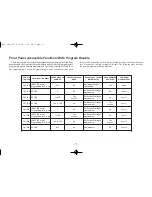
Page 17: ... PROTECTED VALUE MENU OPERATOR ACCESS AT MAIN DISPLAY PROGRAM DISABLE LEVEL PROGRAMMING ENABLED OFF EN INACTIVE or Not Programmed for Pro dis ALL No All displayed values changeable None Yes OFF EN ACTIVE 0 No Per Access Privileges programmed Level 1 No OFF EN ACTIVE 1 to 99 Yes W code Per Access Privileges programmed Level 1 No OFF EN ACTIVE 100 to 199 No Per Access Privileges programmed Level 1 Y...

Page 18: ...ue The two methods for changing numeric data values are digit entry and auto scrolling Digit Entry If the preset entry method has been set to digit entry the least significant digit will blink Pressing the C key multiple times will select other digits Pressing the B key will increment the selected digit The data value will be entered when the A key is pushed or the old value will be retained if no...

Page 19: ... time elapses and the main output deactivates If not selected Auto reset occurs when the main output is triggered Continue Timing at Main Output The timer continues timing when main output is triggered To stop timing the Run Stop terminal is put into the Stop state This mode is useful for repetitive auto cycling applications Stop Timing at Main Output The timer will stop when the main preset s out...

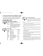
Page 20: ...set 1 Latched Output Continue Timing at 01 Manual Reset to Zero Timed Output Stop Timing at 01 Manual Reset to Zero Timed Output Continue Timing at 01 Manual Reset to Zero Latched Output 18 9 17 8 16 7 15 6 14 5 13 4 12 3 11 2 10 1 SINGLE PRESET OPERATING MODES RESET TYPE RESET OUTPUT 1 Single Preset Modes Manual Auto To Zero To Preset 1 at Timed Output End Latched Timed 1 2 3 4 5 6 7 8 9 10 11 12...

Page 21: ... at 02 Manual Reset to Zero 01 and 02 Timed Continue Timing at 02 Manual Reset to Zero 01 Timed 02 Latched Continue Timing at 02 Manual Reset to Zero Latched Outputs 18 17 16 15 14 13 12 11 10 9 8 7 6 5 4 3 2 DUAL PRESET OPERATING MODES 1 OUTPUT 1 01 off at 02 18 17 16 15 14 13 12 11 10 9 8 7 6 5 4 3 2 1 Timed Latched CONTINUE Timing at 02 at Timed Output 2 End To Preset 2 To Zero Auto Manual Dual...

Page 22: ... to Preset 2 01 Timed 02 Latched Stop Timing at 02 Manual Reset to Preset 2 Latched Outputs Stop Timing at 02 Manual Reset to Zero 01 off at 02 02 Timed Stop Timing at 02 Manual Reset to Zero Latched Outputs Stop Timing at 02 Manual Reset to Zero 01 Timed 02 Latched Stop Timing at 02 Manual Reset to Zero 01 and 02 Timed Stop Timing at 02 Manual Reset to Zero 01 off at 02 02 Latched 39 38 37 36 35 ...

Page 23: ...rS PRS y rSt P uP no Ac PrS PRS y y PrESEt PRS 2 2 0 PltrAc PRS 2 no PrESEt PRS 1 1 0 MODE DESCRIPTION L Locked Preset is not viewable at main display or in Protected Value Menu The Preset can only be viewed or changed in the Programming Menu y n P Protected Value Preset value is viewable and changeable in Protected Value Menu only It is not viewable at Main Display Single Preset Model Dual Preset...

Page 24: ...s whether or not the Output Logic is reversed for all Preset Outputs Programming Keys C Selects Output being configured as indicated by the number on the left of the bottom display line B Selects Output Logic mode for selected Output Ac Out L Ac Out L L OutrES 0 01SEC rEVOut n rEVOut n n OutPut 1 t 0 10 OutPut 2 t 0 10 MODE DESCRIPTION L y n P Protected Value Output Time Value is viewable and chan...

Page 25: ...ivated the main display will freeze and remain frozen until user input is released See Note 1 Store Reset Level Active Reset When the user input is activated the timer display will freeze and the internal Timer value will reset The timer value will be frozen and internally held reset as long as the user input is held active See Notes 1 and 2 Reset Level Active When the user input is activated the ...

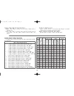
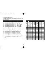
Page 26: ...ailable value USrIn3 rSt L USr F1 rSt L CodE 0 USrIn2 rSt L CODE VALUE DESCRIPTION 0 Programming is Disabled and Code entry display is not available when Program is Disabled 1 99 Protected Parameter Menu appears when Code is entered and Program is Disabled 100 199 Programming Menu appears when code is entered and Program is Disabled USrIn1 rSt L ScroLL no MODE DESCRIPTION no Disables or turns off ...

Page 27: ...d Even Parity 7 data bits 24n 2400 Baud No Parity 8 data bits 24o 2400 Baud Odd Parity 7 data bits 24E 2400 Baud Even Parity 7 data bits 48n 4800 Baud No Parity 8 data bits 48o 4800 Baud Odd Parity 7 data bits 48E 4800 Baud Even Parity 7 data bits 96n 9600 Baud No Parity 8 data bits 96o 9600 Baud Odd Parity 7 data bits 96E 9600 Baud Even Parity 7 data bits MODE MODE DESCRIPTION no YES Unit sends S...

Page 28: ... OPEr TIMER RESET AT POWER UP TIMER OPERATING MODE no 11 PRESETS 2 1 Ac PrS ACCESS PRESET VALUE y y PrESEt PRESET 1 VALUE 1 0 PrESEt PRESET 2 VALUE Dual Preset only 2 0 P1trAc P1 TRACK P2 Dual Preset only no FACTORY SETTINGS CHART OUTPUTS USER INPUTS 2 1 Ac Out ACCESS OUTPUT TIME VALUES L L OutrES OUTPUT RESOLUTION 0 01SEC OutPut OUTPUT 1 TIME 0 10 OutPut OUTPUT 2 TIME Dual Preset only 0 10 rEVOut...

Page 29: ...ESET 1 VALUE PrESEt ACCESS PRESET VALUE Ac PrS 2 1 PRESETS TIMER RANGE TIMER RESET AT POWER UP TIMER OPERATING MODE trAnGE rSt P uP OPEr NUMERIC VALUE ENTRY METHOD EntrY PRINT RESET TIMER VALUE PrnrSt PRINT OPTIONS PrnOPt ABBREVIATE SERIAL MNEMONICS SErAbr SERIAL UNIT ADDRESS SErAdr SERIAL BAUD RATE PARITY SErSEt RS 485 SERIAL OPTION Dual Preset only SCROLL DISPLAY ScroLL PROGRAMMING CODE VALUE Co...

Page 30: ... Before serial communication can take place the unit must be programmed to the same baud rate and parity as the connected equipment In addition the loop address number and print options should be known When used with a terminal or host computer and only one unit is employed an address of zero 00 may be used to eliminate the requirement for the address specifier when sending a command If more than ...

Page 31: ...2AH must be sent to clear the input buffer of all units on the line after a transmit value or print request command is sent to a specific unit on the line The C48T will require a maximum of 50 msec to process the asterisk The command string is constructed in a specific logical sequence The C48T will not accept command strings that do not follow this sequence Only one operation can be performed per...

Page 32: ...ending on the actual value it represents The numeric data is right justified without leading zeros When a T command or print request is issued the above character string is sent for each line of a block transmission An extra SP CR LF is transmitted following the last line of transmission from a print request to provide separation between print outs If serial is abbreviated SErAbr YES just numeric ...

Page 33: ...ost computer device or printer check to make sure that the computer or device is configured with the same communication format as the C48T The communication format the C48T will accept is 1 start bit 7 or 8 data bits no parity or 1 parity bit odd or even and 1 stop bit 3 Check the baud rate and parity in the Programming Menu SErSEt parameter and make sure all devices on the line are set to the sam...

Page 34: ... STOP USER INPUT 1 6 7 RS 485 OPTION 3 USER 5 4 12 11 AC AC B 1 2 13 14 A USER INPUT 3 8 DC OUT IN 10 COMM 9 USER INPUT 1 RUN STOP 6 7 O2 SS INPUT 2 N C COMM O1 SS 8 3 USER INPUT 3 5 USER 4 11 12 AC AC DC OUT IN 10 COMM 9 RS 485 OPTION B 1 2 A 14 13 RUN STOP USER INPUT 1 6 7 Figure 15 Connecting to a Host Terminal connection Each C48T is programmed for a different address and all are programmed fo...

Page 35: ...pen relay contacts close at the timer reset signal activating the disinfectant solution pump When the programmed preset is reached timing stops and the relay deactivates turning off the pump controlling the disinfectant solution The C48 Timer s preset cycle time may be changed according to the manufacturer s concentration level of the disinfectant APPLICATION PROGRAMMING 29 APPENDIX A APPLICATION ...

Page 36: ...d User Input 3 Configurable as current sinking active low or current sourcing active high inputs via a single plug jumper Current Sinking active low VIL 1 5 VDC max 22 KW pull up to 5 VDC Current Sourcing active high VIH 3 5 VDC min VIN max 30 VDC 22 KW pull down Run Stop Response Time 250 msec max User Input Response Time 5 msec max 6 TIME ACCURACY 0 01 7 OUTPUTS Output type and quantity model de...

Page 37: ...ata bits or None 8 data bits 9 ELECTRICAL CONNECTION Wire clamping screw terminals 10 ENVIRONMENTAL CONDITIONS Operating Temperature 0 to 50 C Storage Temperature 40 to 70 C Vibration to IEC 68 2 6 Operational 5 to 150 Hz 2 g Shock to IEC 68 2 27 Operational 30 g 10 g relay Operating and Storage Humidity 85 max relative humidity non condensing from 0 C to 50 C Altitude Up to 2000 meters 11 CONSTRU...

Page 38: ...WER UP Err2 DISPLAYED AT POWER UP Err1 DISPLAYED AT POWER UP 1 Data error in timer value detected by processor 1 Data error in programming parameters detected by processor 1 Data error in preset or output time values detected by processor 1 Press A key 1 Press A key 1 Press A key 2 Check signal lines for possible noise sources a Check all programming parameters a Check presets and output time valu...

Page 39: ...for edge triggered momentary reset OUTPUT WILL NOT RESET 1 Verify programming of Access presets parameter 1 Front panel disabled 2 Configure Snk Src jumper 2 User Input Snk Src jumper configured improperly 1 Verify programming of User Input parameter 1 User input not properly programmed TIMER WILL NOT RESET WHEN A MANUAL RESET IS PERFORMED REMEDIES POSSIBLE CAUSE PROBLEMS PRESETS OR OUTPUT TIME VA...

Page 40: ...N STOP USER INPUT 3 COMM DC OUT IN N C O2 SS COMM USER O1 SS V IN SRC AC AC C48TS SINGLE PRESET RELAY AND SOLID STATE OUTPUTS C48TS SINGLE PRESET RELAY AND SOLID STATE OUTPUTS INPUT 2 12 AC 14 A RS 485 OPTION 4 5 AC 11 1 13 3 2 B 9 10 6 8 7 USER INPUT 1 RUN STOP USER INPUT 3 COMM DC OUT IN O1 RLY O1 RLY O2 RLY USER O2 RLY C48TD DUAL PRESET RELAY OUTPUTS C48TD DUAL PRESET RELAY OUTPUTS INPUT 2 12 A...

Page 41: ...TS103 C48TS113 2 Preset Timer Reflective LCD No Yes No RBC48003 C48TD002 C48TD012 2 Preset Timer Reflective LCD No Yes Yes RBC48003 C48TD007 C48TD017 2 Preset Timer Reflective LCD Yes No Yes N A C48TD005 N A 2 Preset Timer Backlit LCD No Yes No RBC48003 C48TD102 C48TD112 2 Preset Timer Backlit LCD No Yes Yes RBC48003 C48TD107 C48TD117 2 Preset Timer Backlit LCD Yes No Yes N A C48TD105 N A PART NUM...

Page 42: ... 36 ...

Page 43: ...s suitable for Customer s use and that such use complies with any applicable local state or federal law b The Company shall not be liable for a breach of the warranty set forth in paragraph a if i the defect is a result of Customer s failure to store install commission or maintain the Product according to specifications ii Customer alters or repairs such Product without the prior written consent o...

Page 44: ...C48T IM D 06 17 DRAWING NO LP0356 C48T cover D_C48TTOCgreen QXD 6 9 2017 9 41 AM Page 4 ...

Reviews: