background image

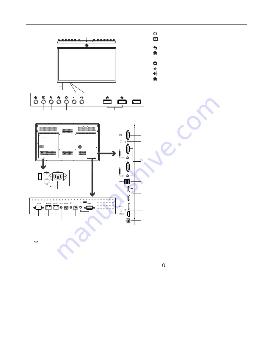
Identification of Controls 

5

1. 

   :

Switch the IFP power on or standby.

2.       : Press the button to display input source menu or 

exit the menu screen.

3.       : Press the button to return to previous menu

.

4

.

      : Press the button to display desktop (Home page) 

on the screen

.

5

.

      : Press the button to open the setting  menu

.

6.       : Press the button to turn down the volume

.

7.       : Press the button to turn up  the volume

.

8.       : USB


for IFP

.

(Android)

9. PC : USB


for OPS

.

Note:

 If no OPS insterted, the USB  port has no function.

10.USB(2.0)(for camera): This port is connected to PC 

(internal OPS) , but is changed to Android if current 
source is AV, USB or in Home page.

Notes: 

1. Please open the dust cover before being used.

2. It can perfectly support up to the 720p of camera.

1.VGA OUT

The currently selected PC IN 1/2/3 signal output.

2. 

WiFi  antenna  for  transmitting  or  receiving  network 

signal. 

3.PC IN1/2/3

Enable  connection  to  PC  or  other  external  devices 

with VGA/AUDIO ports.

Connect the MIC receiver to the  AUDIO/MIC(PC IN 3) 

jack.

4.USB2.0/3.0

USB


standard


interface

enable


connection


to


USB2.0,  USB3.0  standard


devices

When 

connecting, please select the appropriate port.

5.HDMI1/2 Input

To  connect  with  those  equipments  with  HDMI  or  DVI 

interface.
HDMI1(MHL): Connect an MHL - enabled device such 

as  a  cell  phone  to  this  jack  to  view  the  external 

device’s screen on your IFP. 

HDMI2(ARC):  Connect  an  ARC-enabled  home 

theater receiver to this jack.

6. DP(DisplayPort) Input

Connect an external device to DP out jack.

7.TOUCH1/2 OUT

Output the touch for external devices connected 

to  PCx  or  HDMIx  port  which  support  touch 

system.

Note

:  TOUCH  OUT  2  takes  precedence  over 

TOUCH OUT 1 in default. You can define it to in 

Lock menu.

8.RS232

For  service,  software  upgrades  and  the  other 
uses.

9.WAN IN

The built-in router input port. Connect to the 
external network.

10.LAN OUT

The built-in router output port. Connection to 
another computer or other Internet enabled 
devices.

11.AV IN

Connect an AV  device to this jack.

12.S/PDIF digital audio output

Connect a  digital sound system to this jack.

13.

Connect headphones to this jack. The IFP is the 
current audio output.

14. Power Switch

Push to (

1

) to connect the power, push to (O ) to 

cut off.

Note

:


15. Fuse (12A 250V)
16. AC IN

Plug the AC cord into this jack and into a power 
outlet.(~100-240V 50Hz/60Hz

)

Do not cover the Power switch, it should be 

kept free from coverings so that it can be easily 
and conveniently operated.

1

HDMI 1

(MHL) 

HDMI 2

(ARC)

VGA 1

P

C I
N 1

VGA 2

P

C I
N 2

TOUCH

OUT 1

Remote  Sensor

Power  Indicator

1 2 3 4 5 6 7

8

9

10

3

9 10

11

12

13

7

15

14

2

3

4

5

6

4

7

8

16

2

(For example: ST-700 )

AUDIO/MIC

TOUCH

 OUT 2

PC

Summary of Contents for ST-650U

Page 1: ...Before connecting operating or adjusting this product please read the manual completely Please keep this manual for future reference INSTRUCTION MANUAL Interactive Flat Panel...

Page 2: ...Safety Precautions 2 Important Notice 4 Identification of Controls 5 Remote Control 6 Connections 8 Basic Operations 10 Device Settings 12 Network Settings 13 Menu List Troubleshooting 25 Specificati...

Page 3: ...while watching a program especially on a larger than life IFP Make sure that you place or install the IFP where it cannot be pushed pulled over or knocked down Make sure that you route all cords and...

Page 4: ...wer line surges Power lines An outside antenna system should not be located in the vicinity of overhead power lines or other electric light or power circuits or where it can fall into such power lines...

Page 5: ...n the screen as a fixed blue green or red point These non active pixels do not adversely affect the performance of your IFP and are not considered defects Legal notices FCC Statement 1 This device com...

Page 6: ...layed This is not a malfunction and the unit will recover when the temperature returns to normal Do not leave the unit in a hot or cold location Also do not leave the unit in a location exposed to dir...

Page 7: ...I1 MHL Connect an MHL enabled device such as a cell phone to this jack to view the external device s screen on your IFP HDMI2 ARC Connect an ARC enabled home theater receiver to this jack 6 DP Display...

Page 8: ...Switch to HDMI mode Switch to VGA mode Display or exit the current program information 0 9 number buttons Display desktop Home page on the screen VOLUME UP DOWN Control buttons for USB Multi Media Pla...

Page 9: ...t twoAAAbatteries into the battery compartment Make sure that the and symbols on the batteries match the and symbols in the battery compartment 2 Replace the cover 3 To install remote control batterie...

Page 10: ...work cable Set top box Y W R Y W R VGA OUT AUDIO OUT USB Computer USB HDMI Connect TOUCH OUT with USB cable to PC USB port Connect PC with VGA cable or HDMI cable Please choose the proper method of co...

Page 11: ...SB cable USB cable Note After installation of the driver it can control the external computer by native touch control Only for PC HDMI signal TOUCH OUT 2 takes precedence over TOUCH OUT 1 in default Y...

Page 12: ...the IFP 1 2 3 Turning the IFP on or off Operating the Float menu The first time installation Connect to power source and turn on the IFP the below installation menu page will display on the screen 1...

Page 13: ...d drag the icon to on Home page for shortcut created press and drag the shortcut to X REMOVE for shortcut deleted Go to UC Browser Call the device Settings menu Call applications list Shortcuts you cr...

Page 14: ...nd Restrictions Network Setting Show all apps Daydream setting Display information of the unit To set default input method To set Android keyboard AOSP Note To manually set date and time you should to...

Page 15: ...t UserName admin skip the default password setting as there is no default password then press Login button login IP settings Proxy settings Internal routing setting Reset Internal Router by hardware P...

Page 16: ...rnet Point to Protocol Your ISP will provide you with Login ID and password Usually this option is applicable to DSL service Point to Point Tunneling Protocol Your ISP will provide you with Login ID a...

Page 17: ...at 5GHz Setup Next 2 4GHz Setup Next Method 2 Advanced Mode Input the default UserName admin skip the default password setting as there is no default password then press Login button login Select Adva...

Page 18: ...default UserName admin skip the default password setting as there is no default password then press Login button login Select Advanced Mode Select SETUP then OPERATING MODE Select Gateway then press A...

Page 19: ...ISP doesn t provide a designated IP for you then choose DHCP Client Ethernet Point to Protocol Your ISP will provide you with Login ID and password Usually this option is applicable to DSL service Poi...

Page 20: ...Survey Select your desired WiFi signal Connect Input Password Select from 5G 2 4G Select from 5G 2 4G based on the WAN Interface Method 2 Advanced Mode For example WAN lnterface 5G Next Password Setti...

Page 21: ...as there is no default password then press Login button login Successfully connected to return Select your desired WiFi signal Confirm Site Survey Connect Input Password Select Wireless ISP then press...

Page 22: ...your desired Brightness Adjust the brightness Contrast Adjust the contrast Saturation Adjust the color saturation Hue Adjust the image hue Only for NTSC system Sharpness Adjust the sharpness Picture...

Page 23: ...the USB port on the Android board Power on Source Power on Source Setting in MEMORY mode when the IFP powered on it will automatically switch to the source when it powered off last time otherwise it...

Page 24: ...t USB mode first For instructions on using your USB device refer to the user s manual of your USB device Please name your files in English Otherwise the file names can not be shown correctly Certain t...

Page 25: ...Pause STOP Previous Next on the remote control to operate Note You can also use Play Pause STOP Previous Next on the remote control to operate Previous song Pause Play Show information Show playlist...

Page 26: ...or MKV MOV format Now AB repeat starts To cancel highlight Section replay and toggle it to OFF Adjust the volume Playing settings Previous video Play pause Next video Fast reverse Fast forward AB Sect...

Page 27: ...e sources such as cars neon signs or hair dryers Good picture no sound The sound may be muted Press MUTE again to cancel Audio noise Communication problems may occur if infrared communication equipmen...

Page 28: ...d dimensions shown are approximate 3 Specifications and external appearance may be changed for the sake of improvement PC IN WAN IN LAN OUT S PDIF OUT RS232 TOUCH OUT 1 3 1 2 5 1 1 1 1 1 2 2 8A 65 inc...

Page 29: ...PRINTED ON RECYCLED PAPER...

Reviews: