


RealMan (Beijing) Intelligent Technology Co., Ltd.
74
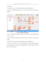
turns to green, and the output status of the corresponding channel is set to high. The
button turns gray when it is released, indicating that the output of the corresponding
channel is low.
Analog Input: This section displays the voltage values of the four analog IO input
channels.
Analog output: This feature can configure the corresponding analog IO output channel
voltage value in range of 0~10V.
8.6.2 Tool I/O Configuration
In the IO interface of the tool panel of the teaching software, the IO status and
configuration of the tool can be displayed. The output voltage of the tool end can be
switched. And simple control of the end gripper can be carried out, as shown in the
figure below.
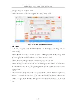
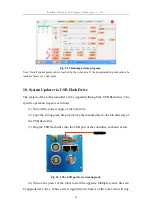
Fig. 8-60 The tool end I/O configuration interface.
Digital Input: This section displays the status of digital IO inputs, with gray circles
representing low inputs and green circles representing high inputs.
Digital output: This part is to configure the digital IO outputs. Press the button and the
color turns to green, and the output status of the corresponding channel is set to high.