background image

Operating instructions 

Peristaltic Pump IP Series

17

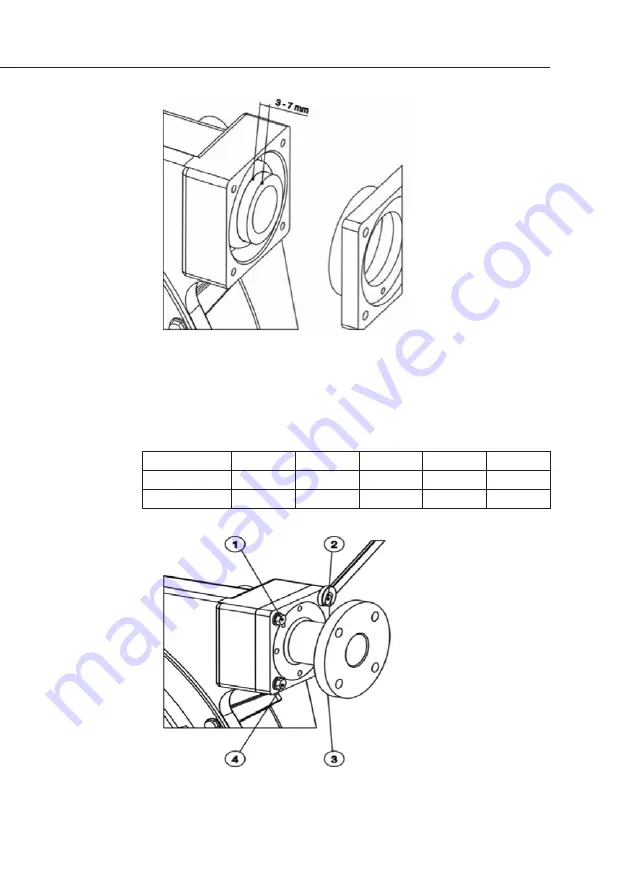
Fig 5: 

Way to proceed 

with the screws 

tightening.

6  Fasten the press flange and the connections to the pump 

casing, tightening progressive the bolts in clock wise (1, 

3, 2, 4, 1, 3, 2, 4, etc.), until the flange becomes totally 

tighten. 

Torque setting

Model

IP-30

IP-40

IP-50

IP-60

IP-70

Press flange

25 Nm

30 Nm

35 Nm

55 Nm

40 Nm

Connection

20 Nm

20 Nm

20 Nm

20 Nm

20 Nm

Fig 4: 

Required distance 

between the end 

of the hose and 

the press ring.

Summary of Contents for IP 30

Page 1: ...Operating instructions IP Series Peristaltic pump ALL THE HOSE PUMP YOU LL EVER NEED...

Page 2: ...oses and accessories reflect what hose pump customers really need and use after all best is what you want second best should never be an option We hope you ll find using your realax pump simple troubl...

Page 3: ...Introduction 2 2 Safety and Responsibility 4 3 Functional description 7 4 Transport and Storage 8 5 Assembly and Installation 9 6 Commissioning 14 7 Maintenance repair malfunctions disposal and spare...

Page 4: ...st accompany it until its demolition The series IP peristaltic pump is a machine destined to work in industrial areas and as such the instruction manual must form part of the legislative dispositions...

Page 5: ...evice The lack of inspections and maintenance They can cause serious damage or injury The person in charge of safety should therefore guarantee that the pump is transported installed put in service us...

Page 6: ...ion Unauthorized access Possible consequence Fatal or very serious injuries Measure Ensure that there can be no unauthor ized access to the unit Hazardous media contamination of persons and equipment...

Page 7: ...are not under pressure and are empty or isolated In the case of the hose becoming stuck during extraction or fitting it is necessary to reverse the direction of the pump relubricate and then repeat t...

Page 8: ...atibility of the cleaning agents with the pump hoses and the hydraulic connec tions Cleaning should be undertaken at the recommended maximum temperature Direction of rotation flow direction Possible c...

Page 9: ...asive shear sensitive and viscose media Typical areas of use include processes where only a low discharge pressure is required max 8 bar 3 1 Construction Main modules Drive Unit Housing Base frame The...

Page 10: ...ose should not be compressed Avoid areas open to harsh weather or excessive humidity For storage periods of longer than 60 days protect the coupling surfaces clamps reducers motors with adequate anti...

Page 11: ...ibutor for high temperature application 5 2 Correct installation of the pump 5 2 1 Suction side The pump is to be positioned as near as possible to the liquid container so that the suction side is kep...

Page 12: ...mp hose A larger diameter is recommend ed in the event of viscose liquids It is recommended to use a flexible transition between two fixed pipes and the hydraulic connection of the pump in order to av...

Page 13: ...The shims are fitted in the factory You can adapt the number of shims to the actual operating conditions according to the following table 5 3 1 IP 30 Model Number of shims of 0 5 mm thickness a NR NBR...

Page 14: ...efault setting if working pressure is not informed b Norprene Bar 1 min 0 19 20 39 40 59 60 79 80 99 0 5 14 14 14 14 14 2 0 14 14 14 14 14 Factoring default setting if working pressure is not informed...

Page 15: ...0 6 6 6 6 6 6 0 7 6 6 6 6 8 0 7 7 7 7 Factoring default setting if working pressure is not informed 5 3 5 IP 70 Model Number of shims of 1 mm thickness a NR NBR EPDM HYPALON NR A and NBR A Bar 1 min...

Page 16: ...perature range Only switch the pump on if it the front cover has been properly attached Check that the rollers are correctly fitted and fastened Check that the pump drive and the inner of the rollers...

Page 17: ...nging the pump hoses 7 2 1 Exchanging the pump hoses refer to section 8 for parts lists and drawings 7 2 1 1 Models IP 30 IP 40 IP 50 IP 70 and IP 70D 1 Close off all valves in order to prevent leakag...

Page 18: ...cover 8 Remove the connections 9 Remove the press flange from the pump casing 10 Remove the pump hose to be exchanged 11 Dismantle the inserts from both pump hose ends 7 2 2 Exchanging the pump hoses...

Page 19: ...tightening progressive the bolts in clock wise 1 3 2 4 1 3 2 4 etc until the flange becomes totally tighten Torque setting Model IP 30 IP 40 IP 50 IP 60 IP 70 Press flange 25 Nm 30 Nm 35 Nm 55 Nm 40...

Page 20: ...tact surfaces to the pump hose with original silicon grease 3 Check the rollers Ensure that the roller surfaces are not damaged 4 Lay the pump hose into the pump casing 5 Attach the inserts at both ho...

Page 21: ...tion 7 2 2 Partial blockage of the suc tion line Clean pipe Insufficient product quantity in storage container Fill storage container or exchange pump Insufficient diameter on the suction side Increas...

Page 22: ...oubt always consult your realax distributor Abnormal elevation of temperature Check rollers shaft mounting Unsuitable lubricant Always consult your realax dis tributor for correct lubricant Insufficie...

Page 23: ...s Description Quantity Reference 1 Pump casing 1 107 00 01 2 Ball bearing box 1 107 00 03 3 Rotor shaft 1 107 00 04 4 Rotor 1 107 00 05 5 Roller support 2 107 00 06 6 Shim 107 00 07 7 Shaft screw 2 10...

Page 24: ...taltic hose NR A 1 107 00 19 Peristaltic hose NBR 1 107 00 20 Peristaltic hose NBR A 1 107 00 21 Peristaltic hose EPDM 1 107 00 22 16 Shaft cap 1 110 00 23 17 Base left 1 100 01 24 Base left S S 1 100...

Page 25: ...or 1 106 00 05 5 Roller support 2 106 00 06 6 Shim 1 mm 106 00 07 Shim 4 mm 106 00 49 7 Shaft screw 2 106 00 08 8 Roller shaft 2 106 00 09 9 Roller 2 106 00 11 10 Metallic cover 1 106 00 13 Metallic c...

Page 26: ...EPDM 1 106 00 22 Peristaltic hose HYPALON 1 106 00 48 Peristaltic hose NORPRENE 1 106 00 50 16 Shaft cap 1 106 00 23 17 Base left 1 106 00 24 Base left S S 1 106 00 44 Base left trolley steel 1 106 00...

Page 27: ...bearing box 1 108 00 02 3 Rotor shaft 1 108 00 03 4 Rotor 1 108 01 04 5 Roller support 2 108 01 05 6 Shim 108 00 06 7 Shaft screw 2 108 00 07 8 Roller shaft 2 108 00 08 9 Roller 2 108 01 09 10 Metalli...

Page 28: ...108 00 22 Peristaltic hose NBR A 1 108 00 23 Peristaltic hose EPDM 1 108 00 24 Peristaltic hose HYPALON 1 108 00 25 16 Shaft cap 1 17 Base left 1 108 00 26 Base left S S 1 108 00 36 18 Base right 1 1...

Page 29: ...0 00 04 4 Rotor 1 110 00 05 5 Roller support 2 110 00 06 6 Shim 1 mm 110 00 07 Shim 7 mm 110 00 55 Shim 5 mm 110 00 56 7 Shaft screw 2 110 00 08 8 Roller shaft 2 110 00 09 9 Separator 4 110 00 10 10 R...

Page 30: ...ic hose HYPALON 1 110 00 54 18 Bearing box cap 1 110 00 23 19 Base left 1 110 00 37 Base left S S 1 110 00 48 20 Base right 1 110 00 38 Base right S S 1 110 00 49 21 Middle 100 mm 1 110 00 39 Middle S...

Page 31: ...l bearing box 1 111 00 03 3 Rotor shaft 1 111 00 04 4 Rotor 1 112 00 02 5 Roller support 2 112 00 03 6 Shim 112 00 04 7 Shaft screw 2 112 00 05 8 Roller shaft 2 112 00 06 9 Roller 2 112 00 07 10 Front...

Page 32: ...00 22 Peristaltic hose HYPALON 1 112 00 23 16 Shaft cap 1 111 00 08 17 Base left 1 112 00 24 Base left S S 112 00 36 18 Base right 1 112 00 25 Base right S S 1 112 00 37 19 Base middle 2 112 00 26 Ba...

Page 33: ...l bearing box 2 111 00 03 3 Rotor shaft 2 111 00 04 4 Rotor 2 112 00 02 5 Roller support 4 112 00 03 6 Shim 112 00 04 7 Shaft screw 4 112 00 05 8 Roller shaft 4 112 00 06 9 Roller 4 112 00 07 10 Front...

Page 34: ...00 49 Base middle S S 2 112 00 54 19 Dual shaft 1 112 00 46 20 Stud 4 112 00 44 21 Driver 1 22 Ball bearing anterior 4 111 00 28 23 Ball bearing posterior 1 111 00 29 24 Ball bearing roller 4 112 00...

Page 35: ...33 9 Declaration of Conformity...

Page 36: ...the lubricant as these are elements that have a normal function wear irrespective of their duration This guarantee is valid as long as the equipment is operated in accord ance with this document This...

Page 37: ...tions sur les pompes p ristaltiques realax contactez Site de Plaisir AxFlow SAS 87 rue des Poiriers Sainte Apolline BP 72 78 372 PLAISIR CEDEX T l 33 0 1 30 68 41 41 Fax 33 0 1 30 68 41 00 Site de Not...

Page 38: ...pl www axflow pl F r mer information om realax slangpumpar v nligen kontakta AxFlow AB Ostm stargr nd 12 120 40 rsta Box 90162 120 22 Stockholm Telefon 08 602 22 00 Fax 08 91 66 66 E post kundservice...

Page 39: ...nit 9a Fieldhouse Business Park Old Fieldhouse Lane Huddersfield HD2 1FA Phone 44 0 1484 543649 AxFlow Durham Unit 31 Evans Business Centre Aycliffe Business Park Newton Aycliffe County Durham DL5 6ZF...

Page 40: ...AHQ OM EN 0304 1013 www realaxpumps com ALL THE HOSE PUMP YOU LL EVER NEED...

Reviews: