


15
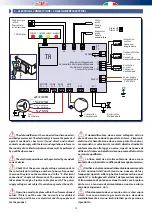
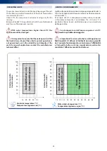
Tabella D - Collegamenti elettrici da effettuare
Collegamenti
Alimentazione elettrica 230 V - 50Hz
cavo 3x1,5mmq
Consenso ventilazione
morsetti COM-C1
cavo 2x1,5mmq
Consenso esterno - deumidificazione
morsetti COM-C2
cavo 2x1,5mmq
Consenso integrazione
morsetti COM-C3
cavo 2x1,5mmq
Uscita allarme (opzionale)
morsetti ALL
cavo 2x1,5mmq
ALIMENTAZIONE
Portare e collegare con cavo 3x1.5mmq i 3 morsetti:
Fase (F)
Neutro (N)
Terra
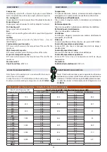
SCELTA DELLA VELOCITÀ DEL VENTILATORE
La macchina viene normalmente fornita con il collegamento
sulla velocità “MIN ” - minima (filo rosso+ filo bianco).
Le altre velocità si ottengono utilizzando assieme al
comune (filo bianco) il filo blu oppure quello nero.
Utilizzare la macchina con portate maggiori alla
nominale non comporta alcun vizio funzionale ma cambiano
le condizioni dell’aria in uscita rispetto a quelle dichiarate.
Non scendere a portate inferiori a 200 mc/h d’aria
in quanto la macchina potrebbe lavorare a temperature
troppo elevate.
FORZATURA DELL’UNITA IN SOLA VENTILAZIONE
Sono disponibili sulla scheda elettronica di controllo del
deumidificatore due morsetti che permettono di far funzionare
l’unità nella modalità di sola ventilazione.
La chiusura del “consenso ventilazione” attiva il ventilatore.
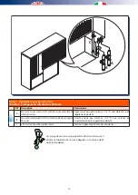
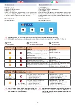
Le indicazioni sui principali collegamenti elettrici che
devono essere effettuati da parte dell’installatore sono
riportati sul dorso del coperchio del quadro elettrico.
CONSENSO INTEGRAZIONE
L’integrazione potrà essere avviata solo se saranno stati
effettuati correttamente i collegamenti del consenso remoto
(ad es. termostato, controllo remoto a microprocessore, ecc.).
A tale riguardo attenersi scrupolosamente a quanto riportato
nello schema elettrico. Nel caso non fosse disponibile alcun
consenso remoto ponticellare i relativi morsetti.
La temperatura di uscita dell’aria non è tarabile.
Table D - Electrical connections to be made
Connections
Electrical power supply 230 V - 50Hz
Cable 3x1.5mm²
Ventilation consent
Terminals COM-C1
cable 2x1,5mmq
External consent - dehumidification
Terminals COM-C2
cable 2x1,5mmq
Integration consent
Terminals COM-C3
cable 2x1,5mmq
Alarm output (optional)
Terminals ALL
cable 2x1,5mmq
POWER SUPPLY
Connect the 3 terminals with 3x1.5mm³ cable:
Phase (F)
Neutral (N)
Earth
CHOOSING THE FAN SPEED
The machine is normally supplied with the connection on the
“MIN” - minimum speed (red wire + white wire).
The other speeds can be obtained using the blue or
black wires together with the common wire (white
wire)
Using the machine with flow rates which exceed the rated flow rate
does not lead to any operating defect but the outlet air conditions
change compared to the declared ones.
Do not use air flow rates lower than 200 m³/h as the
machine could work at temperatures which are too high.
FORCING THE UNIT IN VENTILATION MODE ONLY
Two terminals are available on the dehumidifier circuit board
which allow the unit to be operated in ventilation mode only.
The closure of the “ventilation consent” activates the fan.
Information about the main electrical connections which
must be made by the installer is shown on the back of the
electrical panel cover.
INTEGRATION CONSENT
Integration can be activated only if remote consent connections
have been carried out properly (e.g. thermostat with microprocessor,
etc.). Please, follow the instructions reported on the electric
diagram. In case no remote consent is available, use a jumper
between the relevant terminals.
Output air temperature is not setable.
Summary of Contents for RNW 214-I
Page 2: ......
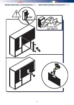
Page 10: ...10 2 3 1 2 POSITIONING OF THE DEHUMIDIFIER 2 INSERIMENTO E FISSAGGIO DEL DEUMIDIFICATORE ...
Page 26: ...26 NOTES ...
Page 27: ......


