RDS PS 8000 Operation Download Page 4

1 - Overview

Overview

This manual covers the operation of the Pro-Series 8000 when configured as an Apollo

8000  Variable-Rate  Spray  Controller.  Separate  manuals  are  supplied  for  other

applications.  The  "Delta  34"  instrument  has  identical  sprayer control  functions  and

capabilities with the exception of Data Logging. This menu is not available.

1.1 

The RDS Precision Farming System (Apollo only)
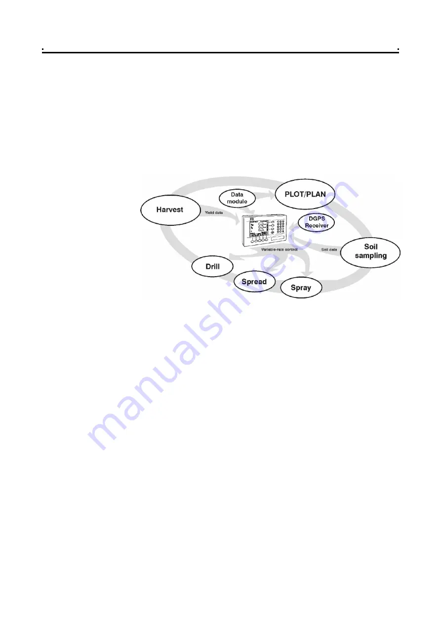
The RDS

PS 8000

is a fully DGPS compatible, multi-function cab computer for a wide

range  of  applications  and  is  the  central  component  of  RDS Precision  Farming

hardware (figure 1). 

1.2 

Installation and Inter-operability with other systems (Apollo  


only)

An  RDS control system comprises several component kits. This  modular approach

means  that  a  suitable  control  system  can  be  specified  for  a  very  wide  range  of

implements. When re-configured with the appropriate control software the 

PS  8000

head unit can be simply transferred between different implements. 

The 

PS  8000 

can  also  output  variable-rate  instructions  to  other  control  systems

including Vicon, Bogballe and  Amatron systems, as well  as acting on variable-rate

instructions  received  from  Fieldstar,  Soyl Opti, Agrocom ACT  and  Hydro-N Sensor

systems.

1.3  

Control Software (Apollo only)

Your instrument is pre-loaded with "Apollo Sprayer Control" software only. 

With the purchase of a "secondary software module" - an electronic chip  loaded into

the  back  of  the  instrument,  the  Pro-Series  can  be  instantly  switched  to  perform

another function e.g. from a Sprayer Controller to a Data Logger for route navigation

and  soil  mapping  tasks.  This  is  done  from  "

Instrument  Select

"  in  the  "USER

OPTIONS" menu.

There  are  software  modules  for  yield  monitoring/mapping,  route/soil  mapping,

variable-rate  sprayer control, variable-rate  belt  spreader  control, variable-rate  disc

spreader control, and variable-rate seed drilling.  

For information on connecting and configuring RDS PF

hardware

e.g. the Data Card

Module, Secondary Software Module, DGPS Receiver, cables etc, and data transfer

to your PC, please refer to the  "Precision Farming Supplement".

1

Figure 1

The Pro-Series 8000 is the

central component of RDS

Precision Farming hardware 


      4   

Summary of Contents for PS 8000

Page 1: ...PS 8000 APOLLO DELTA 34 SPRAYER CONTROLLER Operation RDS Part No Doc Issue Software Issue S DC 500 10 221 4b 10 8 01 PS515 002 rev 27 Apollo PS521 000 rev 10 Delta 1...

Page 2: ...and functions of the Precision Farming System the System are limited as set out in the specification of the System details of which are contained in the Help files and product literature and which mus...

Page 3: ...2 Using the Nozzle Wizard 15 2 3 3 Editing a Preset Nozzle Type 15 2 3 4 Programming the Product Density 16 2 4 Automatic Rate Control 17 2 4 1 Setting the Target Rate 17 2 4 2 Overriding the Target r...

Page 4: ...iable rate instructions to other control systems including Vicon Bogballe and Amatron systems as well as acting on variable rate instructions received from Fieldstar Soyl Opti Agrocom ACT and Hydro N...

Page 5: ...yer fitted with an RDS distribution system On changing sprayers the appropriate tank is enabled from the Machine Options screen in the calibration menu You must re configure the boom setup as required...

Page 6: ...on the PCMCIA card The job summary data is also appended to this file which can be viewed in PLOT PLAN VRT Variable rate treatment Control Mode Apollo only This enables the system to be controlled vi...

Page 7: ...to denote their function 1 6 2 The MAIN screen page Single implement operation The instrument will always default to the MAIN screen on startup The MAIN screen displays the following information figur...

Page 8: ...No Module Module but no card OK iii if a GPS signal is being received Apollo only No Position Standalone No Diff Full DGPS iv if the area distance is being accumulated Apollo Delta 34 No accumulation...

Page 9: ...pplication mode AUTO or MAN and alter the target rate AUTO mode or actual application rate MAN mode for each tank Multi tank display and settings From the multi tank page you can alter the target rate...

Page 10: ...ollo only This page controls data logging Field Summary data and P F functions when the Data Card Module is connected and enabled and data transfer e g printing a job summary 1 Overview Figure 6 The I...

Page 11: ...to select the required letter Some keys have additional special characters not shown on the key legend The key will either toggle between lower and upper case characters or when preceeding a numerica...

Page 12: ...lease refer to the Calibration manual The units are Function Units Metric U K Imperial ForwardSpeed k m hr miles hr Application rate l itres ha g allons acre Flow rate l itres min gallons min Part Tot...

Page 13: ...own arrow key move the screen cursor opposite the product for that tank figure 9b For any tank you can programme and calibrate up to 8 different products A to H NOTE 2 By default the products are labe...

Page 14: ...rget Speed The centre of the bow tie display indicates the target speed for optimum nozzle performance The operating range of the nozzle is based on the target speed There are 8 pre programmed ISO sta...

Page 15: ...arted with the sprayer stationary To stop speed simulation press the key or move the vehicle a short distance 2 3 2 Using the Nozzle Wizard 1 Set your Target Speed as above 2 Key in the target applica...

Page 16: ...ensity for the selected product is anything other than 1 00 the instrument will display the icon on the main screen 1 Press to select the SETUP screen 2 Press to select the PRODUCT SELECTION screen fi...

Page 17: ...instrument will beep continuously Press any of the lower OK keys to cancel the alarm screen and return to the MAIN operating screen An alarm bell icon in the upper right hand corner of the screen will...

Page 18: ...ill beep continuously Press any of the lower OK keys to cancel the alarm screen and return to the MAIN operating screen An alarm bell icon in the upper right hand corner of the screen will continue to...

Page 19: ...screen cursor using the arrow keys and enter values via the numeric keypad 4 Press to reset to the full tank volume 5 Confirm the alarm volume is OK typically the volume needed to spray a single bout...

Page 20: ...nction In addition the area and volume will be recorded to the TOTAL memoryregister 1 Select the INFO screen to display the accumulated totals and the RPM display NOTE If more than one tank is enabled...

Page 21: ...ficient pump capacity low pump speed low or empty tank blocked filters or incorrect jets Press any of the lower OK keys to cancel the alarm screen and return to the MAIN operating screen An alarm bell...

Page 22: ...k session in the internal memory and subsequently download directly to a PC or print to an RDS ICP200 In Cab Printer The amount of summary data for each job is small and it is saved in the internal me...

Page 23: ...the appropriate farm field description in turn from the lists NOTE If a treatment plan is to be loaded and there is more than one machine i e distribution system enabled the SELECT MACHINE page is no...

Page 24: ...al the treatment rate will revert to the Base Rate specified in the plan Application Rate Outside the Field Boundary If you go outside the field boundary but are still within the treatment rectangle a...

Page 25: ...dual requirements e g Operator name Wind Speed Air Temperature Growth Stage Product etc Entering extended data is optional The functions are F1 to F12 by default You can re programme the default funct...

Page 26: ...nt position If you selected the LOG TREATMENT option from the LOG screen page the track data is saved to a dynamic logging file on the data module which can then be viewed in PLOT PLAN 3 2 7 Display G...

Page 27: ...3 Select the logging option LOG TREATMENT 4 When prompted enter the FARM NUMBER and FIELD NUMBER reference The EXTENDED DATA FUNCTIONS page is then displayed If you don t wish to programme any extend...

Page 28: ...ge is displayed fig 17 3 Select the logging option LOG SUMMARY ONLY 4 When prompted enter the FARM NUMBER and FIELD NUMBER reference The EXTENDED DATA FUNCTIONS page is then displayed If you don t wis...

Page 29: ...lected summary 3 5 2 Summary Data Formats You can download the data to Data Card Module Each summary is saved as a text file e g JOB0001 TXT and is formatted the same as a printed job ticket ICP 100 o...

Page 30: ...ues Comments Operator Transmit Time and Date Not included in CSV format 3 5 3 Select and Print Download Job Summaries 1 From the View Data page fig 26 27 press the key 2 Press to select the last summa...

Page 31: ...7 12 99 Full document update p 1 26 inc for software version PS504 010 Issue 3 20 3 01 Update for S W PS515 002 ver 004 Issue 4 19 7 01 U pdate for S W PS515 002 rev 25 Delta 34 Issue 4b 10 8 01 PF r...

Reviews: