LB METRO
38
Sterzo
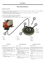
Lo sterzo é azionato da una catena 1 (fig. 7), che trasmette il moto dal pignone di rinvio 2 (fig. 7) alla corona 3 (fig. 7) sulla ruota
anteriore. Al pignone di rinvio 2 il moto viene trasmesso dal pignone 5 (fig. 7), calettato al volante mediante la doppia catena 4
(fig. 7). Per registrare il gioco che si puó creare sul volante guida, spostare i supporti dei pignoni 2 e 5 agendo sulle viti 6 (fig. 7).
Fig . 7
1.
Catena
2.
Pignone di rinvio
3.
Corona
4.
Doppia catena
5.
Pignone
6.
Viti registro supporto pignoni
Fig. 7
1.
Chain
2.
Transmission sprocket
3.
Crown gear
4.
Double chain
5.
Sprocket
6.
Sprocket support adjusting screws
Tek. 7
1.
Ketting
2.
Transmissiewiel
3.
Kroon
4.
Dubbele ketting
5
Tandwiel
6
Regelschroeven tandwiel steun
Fig. 7
1.
Chaîne
2.
Pignon de renvoi
3.
Couronne
4.
Double chaîne
5.
Pignon
6.
Vis de réglage support pignons
Steering
The steering system is operated by a chain 1 (fig. 7)
which transmits motion from the transmission
sprocket 2 (fig. 7) to the ring gear 3 (fig. 7) on the
front wheel. The transmission sprocket 2 is driven
by the sprocket 5 (fig. 7) keyed to the steering wheel
by means of the double chain 4 (fig. 7). To adjust
any backlash which may occur on the steering wheel,
move the supports of the sprockets 2 and 5 using the
screws 6 (fig. 7).
Besturing
De besturing wordt geregeld door ketting 1 (tek. 7)
die de beweging van transmissiewiel 2 (tek. 7) naar
kroon 3 (tek. 7) op het voorwiel overbrengt.
De beweging wordt naar transmissiewiel 2
overgebracht door tandwiel 5 (tek. 7) dat aan het
stuurwiel bevestigd is met dubbele ketting 4 (tek. 7).
Om de speling op het stuurwiel te regelen, de steunen
van tandwielen 2 en 5 verplaatsen met behulp van
schroeven 6 (tek.7).
Direction
La direction est actionnée par une chaîne 1 (fig. 7)
qui transmet le mouvement du pignon de renvoi 2
(fig. 7) à la couronne 3 (fig. 7) de la roue avant. Au
pignon de renvoi 2 le mouvement est transmis par le
pignon 5 (fig. 7) relié au volant par l'intermédiaire de
la double chaîne 4 (fig. 7). Pour régler le jeu
éventuellement présent au niveau du volant de
commande, déplacer les supports 2 et 5 en
intervenant les vis 6 (fig. 7).
Summary of Contents for 33.LB.Metro
Page 2: ......
Page 70: ...LB METRO 68 ...


