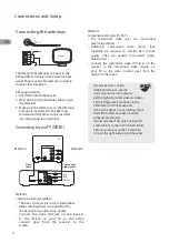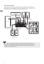
Connecting the antennas
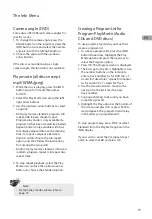
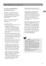
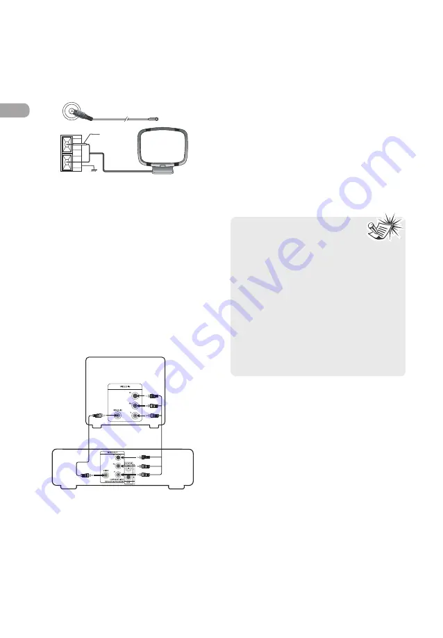
The AM and FM antennas connect to the
AM and FM terminals on the system’s back
panel. They must be hooked up in order to
receive clear reception.
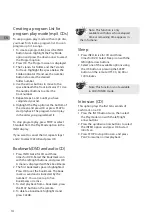
AM Loop Antenna
1. Uncoil the AM Antenna wire.
2. Press down on the Antennas tab to open
the terminal.
3. Make sure the white wire on the AM loop
antenna is inserted into the AM loop
terminal and the other wire is inserted
into the ground loop terminal.
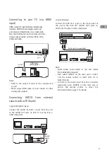
Connecting to your TV (VIDEO)
2
EN
Connections and Setup
FM 75
Ω
Whit e
Antenna
GN D
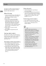
Method 2
Component video jacks (Pr, Pb, Y)
• The component video jacks are color-coded
green, blue and red.
• Additional component video cables (not
supplied) are required to provide best picture
quality. They are usually color-coded green,
blue and red.
• Connect the component video OUT jacks on the
receiver to the component video IN jacks on
your TV so the video content goes from the
receiver to the screen.
Method 1
Composite video jack (yellow)
• The basic video jack is color-coded yellow.
• Video cable (yellow) is supplied for the
connection for good picture quality.
• Connect the video OUT jack on the receiver
to the IN jack on your TV so the video
content goes from the receiver to the
screen.
• If your television is a high
definition television, use the
unit's progressive scan output to
get the highest possible video resolution.
Set the Progressive Scan option in the
Video menu to On (See page 22).
• If one of the devices is not working, check
that all the cables have been inserted
properly into the jacks.
• If your component has only one input for
audio (mono), connect it to the left (white
L/Mono) audio jack on the TV and don’t
connect the right audio part of the cable.
TV
Red
Blue
Green
VIDEO OUT
1
Video
cable
Component
video cable
Method 1
Method 2
Summary of Contents for RTD317
Page 35: ......


