background image

Copyright © 2015 RCA Communications Systems

RPX4500/RPX4600   P25 PORTABLE RADIO – USER MANUAL

3

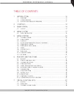
TABLE OF CONTENTS

1. INTRODUCTION ..............................................................................10

1.1. OVERVIEW ....................................................................................................... 10
1.2. CONFIGURATION .............................................................................................. 10
1.3.  MODES OF RPX4600 P25 OPERATION .............................................................. 11

2. CONTROLS .....................................................................................12
3.  MAIN SCREEN ................................................................................14

3.1. LAYOUT ............................................................................................................ 14

4.  MENU SYSTEM ...............................................................................17

4.1.  MENU NAVIGATION ......................................................................................... 18

5.  MENU SCREENS .............................................................................20

5.1.  CHANNEL SCREEN ............................................................................................ 20
5.2.  ZONE SCREEN .................................................................................................. 21
5.3. SQUELCH ......................................................................................................... 21
5.4.  MUTE ADJUST/MONITOR (ANALOG CHANNELS) .............................................. 22
5.5.  PHONEBOOK SCREEN ....................................................................................... 23
5.6.  PHONEBOOK EDIT SCREEN ............................................................................... 24
5.7. SETUP ............................................................................................................... 27
5.8.  STORED CALLS ................................................................................................. 33
5.9. MESSAGES ....................................................................................................... 34
5.10.  SCAN EDIT MENU ............................................................................................. 39
5.11.  NO MENU ........................................................................................................ 41

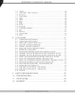
6.  FEATURES AND FUNCTIONS ...........................................................41

6.1. BATTERY 

.......................................................................................................... 41

6.2.  SWITCH ON/SWITCH OFF ................................................................................. 42
6.3.  CHANNEL SELECTION ....................................................................................... 43
6.4.  ZONE SELECTION .............................................................................................. 43
6.5.  THREE POSITION FUNCTION SWITCH ................................................................ 43
6.6.  RECEIVING (SINGLE CHANNEL SCREEN) ............................................................ 43
6.7. TRANSMITTING ................................................................................................ 44
6.8.  SCAN FUNCTIONS ............................................................................................ 44
6.9.  KEYPAD LOCK .................................................................................................. 46
6.10. ENCRYPTION .................................................................................................... 46
6.11.  EMERGENCY ALARM ....................................................................................... 46
6.12.  CONNECTING AUDIO ACCESSORIES ................................................................ 47

7.  SPECIAL FUNCTION KEYS ...............................................................47

7.1. ALARM ............................................................................................................. 47
7.2. ANNOUNCE ..................................................................................................... 47
7.3.  CHANNEL UP AND DOWN ................................................................................ 48

Summary of Contents for RPX4500U

Page 1: ...PX4500U UHF 400 480 MHz RPX4500U2 UHF 440 520 MHz Communications Systems U S E R M A N U A L RPX4600 Series 7 Function Keys Full Keypad w Display RPX4600V VHF 136 174 MHz RPX4600U UHF 400 480 MHz RPX4600U2 UHF 440 520 MHz RCA P25 Portable Radios 5Watts IP67Submersible ...

Page 2: ...able form without prior written permission from RCA DISCLAIMER There are no warranties extended or granted by this document RCA accepts no responsibility for damage arising from use of the information contained in the document or of the equipment and software it describes It is the responsibility of the user to ensure that use of such information equipment and software complies with the laws rules...

Page 3: ...TOR ANALOG CHANNELS 22 5 5 PHONEBOOK SCREEN 23 5 6 PHONEBOOK EDIT SCREEN 24 5 7 SETUP 27 5 8 STORED CALLS 33 5 9 MESSAGES 34 5 10 SCAN EDIT MENU 39 5 11 NO MENU 41 6 FEATURES AND FUNCTIONS 41 6 1 BATTERY 41 6 2 SWITCH ON SWITCH OFF 42 6 3 CHANNEL SELECTION 43 6 4 ZONE SELECTION 43 6 5 THREE POSITION FUNCTION SWITCH 43 6 6 RECEIVING SINGLE CHANNEL SCREEN 43 6 7 TRANSMITTING 44 6 8 SCAN FUNCTIONS 44...

Page 4: ...LE CHARGER VCH4501 51 8 7 BATTERY BELT CLIP BC4500 51 8 8 VHF MOULDED ANTENNA 136 300 MHZ ANH4500V 136 300 51 8 9 WIDEBAND UHF WHIP ANTENNA 440 500 MHZ ANH4500U 6 440 500 51 8 10 WIDEBAND UHF WHIP ANTENNA 400 480 MHZ ANH4500U 6 400 480 51 8 11 STUBBY UHF WHIP ANTENNA 400 480 MHZ ANH4500U 3 400 480 52 8 12 HEAVY DUTY SPEAKER MICROPHONE IP56 SM310 X43 52 8 13 HEAVY DUTY WATERPROOF SPEAKER MICROPHONE...

Page 5: ...s material unless the radio s level of IECEx approval is approved for use in that area Obey the Turn Off Two way Radios signs where they are posted e g in a fueling station Do NOT touch the antenna while the radio is transmitting Do NOT dispose of batteries in a fire Dispose of batteries according to local recycling regulations Do not dispose as household waste Do NOT attempt to disassemble the ba...

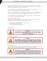
Page 6: ... must become acquainted with the safety precautions and first aid instructions On the label of the container in which it was supplied On the Material Safety Data Sheet In any local Safety Orders and Regulations WARNINGS Lithium Batteries WARNING LITHIUM BATTERIES THIS EQUIPMENT USES LITHIUM ION BATTERIES REFER TO THE APPROPRIATE MATERIAL SAFETY DATA SHEET MSDS FOR SAFETY INFORMATION Radio Frequenc...

Page 7: ...ng garage or underpass GENERAL NOTES PLEASE NOTE Configuration is dependent upon the specification by the customer when the equipment was ordered and installed CONVENTIONS Where the word generally or may is used to describe a facility this operation is an option that may be enabled with your Programming Software PS In some cases key functions will be determined by the customer configuration When a...

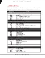
Page 8: ...sor DTMF Dual Tone Multi Frequency FCC Federal Communications Commission FM Frequency Modulation GPS Global Positioning System ICNIRP International Commission on Non Ionising Radiation Protection ID Identification IEC International Electrotechnical Commission IEEE Institute of Electrical and Electronic Engineers IP Internet Protocol LED Light Emitting Diode LMR Land Mobile Radio NAC Network Access...

Page 9: ...5 signal regardless of NAC or TGID will be heard MPT1327 A signaling standard for Trunked Private Land Mobile Radio Systems Defined for systems in the UK but also used outside the UK Issued January 1988 Muted Audio is prevented from being heard through the speaker NAC Network Access Code Used as a filter where multiple networks may share a common RF frequency Normal Mute Mode of Radio Receiver Onl...

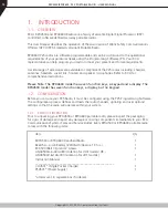
Page 10: ...4600 model has seven function keys a keypad and a display The RPX4500 model has seven function keys a display but no keypad 1 2 CONFIGURATION Before you can use your P25 Radio it must be configured using the P25 Programming Software The configuration process defines and loads the radio channels signaling and user options settings so that the radio will operate within your system 1 2 1 PRODUCT INSP...

Page 11: ...Remove by doing the reverse 1 3 MODES OF RPX4600 P25 OPERATION Your RPX4600 P25 Radio operates in Analog Frequency Modulation FM P25 Conventional Digital and P25 Trunked Digital modes Radio channels are organized in groups of up to 250 per zone Up to 40 zones may be defined Generally zones can be programmed with channels belonging to common function groups A radio channel can be defined as Analog ...

Page 12: ...2 2 CONTROLS The controls of the RPX4600 P25 Portable radio are shown below in Figure 1 Selector Switch ABC Switch On Off Volume Indicator LED Function 5 Function 6 PTT Function 2 Function 1 Antenna Function 7 Accessory Connector Function 3 Function 4 Keypad Figure 1 RPX4600 Portable Layout ...

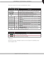
Page 13: ... Programmed Default is Menu Select key Function Key F2 Programmer configurable function key Programmed Default is Chan nel Down key Function Key F3 Programmer configurable function key Programmed Default is Chan nel Up key Function Key F4 OK Programmer configurable function key Programmed Default is OK key Function Key F5 Programmer configurable function key Function Key F6 Programmer configurable...

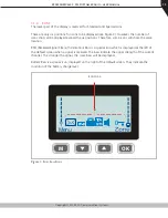
Page 14: ...ciated with the function buttons The soft label text is defined in the PS and can be assigned to the F1 to F4 function buttons Each soft label can be up to five characters 3 1 2 TEXT PANEL The main area of the default screen is the Text Panel which displays textual information This information contains both Persistent and Non persistent text information as follows Persistent Text e g Channel Name ...

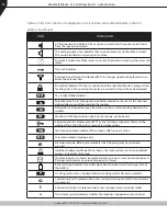
Page 15: ...the six positions Therefore some icons will share the same location RSSI Received Signal Strength Indication Bars is a special icon which is displayed at the left of the default screen when a signal is received The bars indicate the signal strength of the current channel The stronger the signal the more bars will be displayed Battery Bars is a special icon displayed on the right of the default scr...

Page 16: ...ill be heard on the speaker N Normal Mute Only radio signals from the users own network will be heard on the speaker M Monitor All P25 digital radio signals on the channel will be heard Key lock indicator All keys except PTT or any function assigned as Alarm will be disabled Press the OK key for 2 seconds to unlock all keys TA Talk Around enabled indicator When shown Talk Around is active SC Scram...

Page 17: ...e Call Alert Volume Status Location Report Undefined No Menu Entry The presence and order of the above menu selections is determined by your PS configuration The Setup menu is a special case entry Setup is a subgroup that can have any of the menu selections assigned to it This means that less frequently used selections can be partly hidden away under the Setup subgroup but still remain accessible ...

Page 18: ...ly pressing the M key while in a menu will navigate back to the next highest level of menu and the OK key selects the function The keys are generally used to navigate through a list of options such as channels or to increase or decrease a value When the Menu key is first pressed the numeric keys become short cut keys to functions Numeric keys can be programmed with functions using the PS i e Scan ...

Page 19: ...POINT Default Screen Normal Channel Screen Channel Back Back Back Back Back Back Back Back Back Back Back Back Back Back Back Back Back Back Back Back Back Back OK OK OK OK OK OK OK OK OK OK OK Menu 1 Zone Select Note Example menus only shown Other Menus may be configured with the FPP Submenu Submenu Submenu Submenu Submenu Submenu Submenu Key Beeps ON OFF Backlight ON OFF Other User Menu items Mo...

Page 20: ...cess any of the menu options from the Main Setup or User Options Menus use the and keys to scroll through the menu options and then press the OK button when the required menu is displayed Pressing the Back key at any point will go back to the previous screen 5 1 CHANNEL SCREEN The Channel Screen shows the current channel and allows channel selection Pressing the M key enters the Menu mode Radio ch...

Page 21: ...with the PS 5 3 SQUELCH The Squelch menu allows the channel s default squelch mode to be modified If the selected channel is changed or the radio is switched off the channel s default squelch setting will be restored From the main channel screen press the M key to enter Menu Mode Use the keys to scroll through menu options With the Setup menu option displayed press the OK key to access the Setup s...

Page 22: ... will receive any Analog voice or P25 digital signals Digital NAC or Analog Continuous Tone Controlled Sub audible Squelch CTCSS is not checked An M icon on the display indicates Monitor mode 5 3 2 2 Analog Channel Normal Mode When Normal mute is selected the radio will receive correctly addressed Analog radio transmissions and all encrypted or clear digital transmissions An N icon on the display ...

Page 23: ...ress the M key to enter Menu Mode Use the keys to scroll through menu options With the PhoneBook menu option displayed press the OK key to access the PhoneBook screen From the Phonebook screen it is possible to view all of the phone entries in the Phonebook These entries may be Individual Addresses Telephone numbers or Talk Groups When the Phonebook screen is displayed it will show the currently s...

Page 24: ...ert 5 6 PHONEBOOK EDIT SCREEN The Phonebook edit screen provides a method to modify the phonebook entries New entries can be added and existing entries can be modified or removed from the phonebook Phonebook entries may be Individual Addresses Telephone numbers or Talk Groups From the main channel screen press the M key to enter Menu Mode Use the keys to scroll through the menu options With the Ph...

Page 25: ...exit back to the default screen 5 6 2 PHONEBOOK EDIT TO ADD A NEW ENTRY From the Ph Book Edit screen in any phonebook entry press OK and the Ph Book Edit pop up menu will be displayed Use the keys to select Add from the pop up menu and press OK The first of the Add New Entry sub menu screens will be displayed The first sub menu screen is the Entry Type screen There are seven possible types of Phon...

Page 26: ...cted phonebook entry is displayed The System ID entry can then be changed using the numeric digits and key as a destructive backspace If the System ID has to be changed use the keypad and the key to enter the new System ID as required and then press the OK key If the system ID does not have to be changed press the OK key The Edit WACN ID sub menu screen will be displayed 5 6 3 2 WACN Wide Area Cov...

Page 27: ...nged use the keypad and the keys to enter the new IP Address as required and then press the OK key If the IP Address does not have to be changed press the OK key The Edit Name sub menu screen will be displayed 5 6 3 5 Name Upon entering the Edit Name screen the current Name of the selected phonebook entry is displayed The name entry can be changed using the numeric digits and the keys to move the ...

Page 28: ...NS The User Options menu provides access to a list of Functions that may be toggled on or off Up to 10 functions may be defined in this menu by the PS From the Setup menu use the keys to scroll through sub menus and with the User Options menu option displayed press the OK key to access the User Options screen One of the programmable functions will be displayed These functions may include Key Beeps...

Page 29: ...e next highest menu level 5 7 3 ALERT VOLUME The Alert Volume screen allows the user to set the level of the relative Alert Volume level in relation to the current Volume setting The level can be set in 62 steps over the range 31 to 31 with 0 zero being about the same as the voice level For example if the alert volume is set to 6 it will be softer than received voice on the radio From the Setup me...

Page 30: ...ion Key ID key name and the key identifier is displayed The key name and the key identifier 1 32 for the selected channel can be changed using the keys If the selected channel is changed or the radio is switched off the channel s default encryption key will be restored Press the OK key to save the changes and return to the main channel screen Press the Back or M key to save the changes and return ...

Page 31: ...600 P25 PORTABLE RADIO USER MANUAL 31 Application SW Ver Date Application Upgrade Ver Date PLA Code P25 Radio Unit Trunked ID and IP Addr P25 Trunked SysID WACN GID and UID Feature Authorization Enables Encryption Status External Application Memory Status ...

Page 32: ... 1 71 MPT Network 2 72 5 7 7 RSSI RECEIVED SIGNAL STRENGTH INDICATOR The RSSI screen displays the received signal strength in dBm When the radio has been correctly calibrated the reading is typically accurate to within 2 dBm between the range of 120 dBm and 80 dBm For example 90 dBm is a strong signal and 120 dBm is no signal On digital channels the RSSI screen also shows the Bit Error Rate BER RS...

Page 33: ... if configured to return to the default screen 5 8 1 TO CALL BACK A STORED CALL From the Stored Calls screen use the keys to scroll through and select the required stored call record from the list Press the OK key and the stored calls pop up menu will be displayed From the pop up menu use the keys to select the CALL option Press the OK key and the radio will be set to the individual calling mode w...

Page 34: ... press the OK key to access the Messages screen The Messages pop up menu will be displayed 5 9 1 MESSAGES POP UP MENU The Messages pop up menu selections are VIEW Used to view received messages SMSG Short Message The radio can be programmed with a list of predefined messages Selecting SMSG shows a list of predefined short messages which can be sent to another radio unit Only applicable when a digi...

Page 35: ... 1 Messages View Pop Up Menu The Messages View pop up menu selections are DELETE to delete the currently selected message MORE to view the full entire message REPLY to select the method of replying to the selected message Use the keys to select the required option With the DELETE option selected press the OK key to delete the selected message from the radio The radio will return to the Messages Vi...

Page 36: ...s activated an individual voice call is sent to the message sender With the SMSG option selected press the OK key to displays the short message MessagesReply screen With the TXTMSG option selected press the OK key to display the message Reply Text screen Press the M or Back key to return to the next highest menu screen Press the Reset function key if configured to return to the default screen 5 9 ...

Page 37: ...ne position to the left Pressing and holding the Reset key for more than one second will delete all characters from the cursor position to the left until the Reset key is released A new character entered is put on the current cursor location Once the text message is complete press the OK key to send the text message The radio will then return to the default screen Press the M or Back key to return...

Page 38: ...screen appears 5 9 3 2 Destination Select Pop Up Menu This menu allows selection of the message destination The selections are PH BK to select the destination from the phone book ENT ID to enter the destination Unit ID CANCEL to cancel the destination selection Use the keys to select the require option With CANCEL selected press the OK key to return to the previous screen i e Short Message Screen ...

Page 39: ...destination radio is not available 5 10 SCAN EDIT MENU The Scan Edit menu allows the user to add or delete channels to or from a Scan Group Any changes to a Scan Group are stored permanently in the radio From the main channel screen press the M key to enter Menu Mode Use the keys to scroll through menu options With the Scan Edit menu option displayed press the OK key to enter the Scan Group Edit s...

Page 40: ...ority 2 channel will have the second highest priority in the scan group Use the keys to select the priority of the channel and press the OK key The Scan Group Add screen will be displayed Press the M or Back key to return to the next highest menu screen Press the Reset function key if configured to return to the default screen 5 10 2 SCAN GROUP ADD SCREEN The Scan Group Add screen shows channels t...

Page 41: ...l to enter the radio when in use 6 1 2 BATTERY CHARGING Please see the Battery Charger User Manual for Charging Safety Precautions and Operational Guidelines PLEASE NOTE The radio must be turned off prior to charging the battery Battery life will be reduced if the radio is on when placed in the charger Batteries should not be left in a charger for prolonged periods i e 3 day weekend as this will r...

Page 42: ...io will automatically turn off after a predefined duration of inactivity as set by the PS i e no keys pressed The radio will emit warning beeps for 10 seconds prior to switching off Pressing any key will reset this timer 6 2 1 DEFAULT SCREEN TRUNKED MODE Once turned on the radio will show the currently selected Zone and Channel If the selected channel is a trunking channel the radio will scan unti...

Page 43: ...aker Icon will be displayed if a signal is being received that is not addressing this radio and is not audible For example another user group may be having a conversation on another Talk Group when receiving in Selective Mute The analog channel s receive mute setting can be altered from the Mute Adjust menu While on an Analog channel both P25 and Analog FM transmissions will be received While on a...

Page 44: ...g the PTT and commencing to speak This ensures that the path is properly established and avoids lost truncated or distorted speech Use correct operating procedures and keep your transmissions short Release the PTT as soon as you finish speaking The talk group for a transmission is usually associated with a channel selection A talk group will address all others that have the same TGID selected Whil...

Page 45: ...der User Options menu Selecting a channel that is associated to a Voting Group with Scan Vote enabled in the PS starts the voting process The top line of the display still shows the name of the current selected channel The second line of the display shows the name of the current selected zone while scanning voting The channel can be changed by using the keys Other channels may be either Scan or No...

Page 46: ...will receive either clear or encrypted traffic A transmission on this channel will be encrypted When the radio is on an encrypted channel the encryption icon will not be shown if a received signal is not encrypted The current channel s transmit encryption key can be temporarily changed from the Crypto menu When in Analog FM mode there is a simple voice inversion scrambler for low security applicat...

Page 47: ...Please Note The use of an audio accessory may affect the waterproof performance of the radio 7 SPECIAL FUNCTION KEYS Special function keys are simply short cuts to menu screens options Further information on the operation of these function keys is contained in Section 5 This section lists Functions that may be programmed using Function keys F1 to F6 Selected functions may also be programmed into t...

Page 48: ...functions DTMF1 and DTMF2 Send DTMF is only supported in analog mode and can be assigned to keys F1 to F6 If an analog channel is selected and transmit is allowed then activating this function transmits a predefined DTMF sequence up to 16 tones 7 6 KEY LOCK The Keyboard Lock function is dedicated to the OK key To use Key Lock the function has to be enabled through the PS To unlock the keys the OK ...

Page 49: ...re Minimum Mute and Maximum Mute limits 7 11 RESET The reset function performs several tasks In order of priority it Stops Alerts if any Alerts are sounding Performs a Backspace if there is a User entry pending Switches back to the Main Menu if in a lower menu It is used during text entry modes such as Phonebook Edit and Text Messaging for backspacing 7 12 SCAN The Scan key starts and stops the Sc...

Page 50: ...nction key is used to temporarily remove members from a scan channel The removal is temporary only until the channel is changed 7 16 SQUELCH The squelch mode is used to selectively receive P25 signals It has three modes Monitor Normal and Selective When set to Monitor all P25 traffic on that channel will be heard subject to presence of encryption Normal mode will hear all P25 traffic with the corr...

Page 51: ...ank Charger CH4506 PKG Six Bank Charger for up to six portable radios 8 6 Single Unit Vehicle Charger VCH4501 Single radio charger for in vehicle charging using 12V connector 8 7 Battery Belt Clip BC4500 Belt clip for spare batteries 8 8 VHF Moulded Antenna 136 300 MHz ANH4500V 136 300 Uncut includes cutting chart 136 300 MHz 8 9 Wideband UHF Whip Antenna 440 500 MHz ANH4500U 6 440 500 Moulded ant...

Page 52: ...tion keys and man down feature 8 16 Surveillance Kit SK22NE X43 Two wire in ear style 8 17 Noise Reduction Headsets IP56 HS61NR Over the head high noise reduction headsets Requires X43 cord 8 18 Noise Reduction Headsets IP56 HS71NR Behind the head high noise reduction headsets Requires X43 cord 8 19 Holsters Nylon Holster w Fixed Belt Loop RPX4500 HN4500FL Nylon Holster w Swivel Belt Loop RPX4500 ...

Page 53: ...with a fresh one 2 The battery is not properly installed Remove the battery and reattach it The operating time is notice ably shorter than normal even though the battery is properly charged 1 The battery is worn out time to buy a new battery 2 The battery is not fully charged Make sure the battery is removed after the LED indicator has turned green Cannot talk to or hear trans missions from your g...

Page 54: ...o Way Radio 1430 240th St Harbor City CA 90710 Toll Free 800 895 5122 Fax 877 291 9565 Email info dtwr com discounttwo wayradio com 2015 RCA Communications Systems All rights reserved Authorized North American Dealer For more information visit rcacommunicationssystems com Communications Systems TRANSMITTER SPECIFICATION Power Output 0 5 5 W 3 programmable levels Audio Distortion 3 at 1 kHz 60 devi...

Page 55: ...ations or replace the product with a new product of the same make and model The user is responsible for all charges incurred in returning the product to the Authorized RCA Communications Systems Sales and Service Outlet RCA Communications Systems will be responsible for all charges in returning the product to the end user via standard ground shipping service RCA Communications Systems shall have n...

Page 56: ... specifications and design are subject to change without notice due to continuous development No part of this manual may be copied reproduced translated stored in a retrieval system distributed or transmitted in any form or by any means electronic or mechanical for any purpose without the expressed written permission from RCA Communications Systems The end user of any two way radio is solely respo...

Page 57: ...can cause biological damage Very high levels of x rays for example can damage tissues and genetic material Experts in science engineering medicine health and industry continue to work with organizations to develop standards for exposure to RF energy These standards provide recommended levels of RF exposure for both workers and the general public These recommended RF exposure levels include substan...

Page 58: ...tute ANSI IEEE C95 1 1992 IEEE C95 1 1999 Edition Industry Canada RSS 102 RF EXPOSURE COMPLIANCE AND CONTROL GUIDELINES AND OPERATING INSTRUCTIONS To control exposure to yourself and others and to ensure compliance with the Occupational Controlled environment exposure limits always adhere to the following procedures GUIDELINES User awareness instructions should accompany the device when transferre...

Page 59: ...r any other item please contact RCA Communications Systems For Sales Warranty and Customer Support please contact Discount Two Way Radio Corporation North American RCA Distributor 1430 240th Street Harbor City CA 90710 Phone 310 224 5100 Fax 310 224 5101 www DiscountTwo WayRadio com Always keep the radio at least 2 inches 5 cm from your face when transmitting and at least inch 10 mm from the body ...

Reviews: