LCD INSTALLATION AND OPERATION INSTRUCTIONS
Page 27
OPERATING INSTRUCTIONS
1.
STOP!
Read the safety information above. If, at
any time, the appliance will not operate properly,
follow the instructions “TO TURN OFF GAS TO
APPLIANCE”.
2. Set the operating control or thermostat to off or its
lowest setting.
3. Turn off all electric power to the appliance.
4. Close the main manual gas shut-off valve, Figure 16.
5. Wait fi ve (5) minutes to clear out any gas. Then
smell for gas, including near the fl oor. If you smell
gas,
STOP!
Follow “B” in the safety information
above (to the left) on this label. If you do not smell
gas, go to the next step.
6. Remove the upper front jacket panel.
7. Turn the knob on the pilot valve to off, Figure 18.
8. Turn the knob on the main gas valve to off, 225
through 400 models, Figure 18. On 600 through
2300 models close the manual shutoff valve located
in the control compartment, Figure 19.
9. Remove the plug(s) from the pilot and manifold
pressure fi tting(s), Figure 19.
10. Connect a manometer having a minimum capacity
of
20 in
,
508 mm W.C
. to the pilot and manifold
pressure fittings, Figure 19. Make sure the gas
supply piping has been purged of air and all gas
joints up to the gas valve have been thoroughly
checked for leaks.
11. Remove plug(s) from the differential air pressure
taps, Figure 17.
12. Connect both sides of a manometer to the pressure
switch tee, Figure 17, going to one of the pressure
switches.
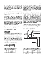
Figure 18 - Pilot Valve (All Models)
Main Valve (225 - 400 Models)
13. Turn the knob on the pilot valve to on, Figure 18.
14. Turn on all electric power to the boiler and set
the operating control or thermostat to the desired
setting.
15. With the unit operating at high purge the differential
air pressure should match those listed in Table
15. To adjust the differential air pressure see the
“AIRFLOW ADJUSTMENT” instructions in the
“CHECKING AND ADJUSTMENTS” section.
Figure 19 - Manual Valve & Manifold Pressure Tap
16. The pilot should automatically light. Do not try to
light the pilot by hand!
17. The pilot pressures should match those listed
in Table 20. To adjust the pilot gas pressure see
the “PILOT ADJUSTMENT” instructions in the
“CHECKING AND ADJUSTMENTS” section.
18. Distinguish pilot.
19. Turn the knob on the main gas valve to on, 225
through 400 models, Figure 18. On 600 through
2300 models open the manual shutoff valve located
in the control compartment, Figure 19.
20. Recycle boiler.
21. The manifold pressures should match those listed
in Table 20. To adjust the manifold gas pressure see
the “GAS PRESSURE ADJUSTMENT” instructions
in the “CHECKING AND ADJUSTMENTS” section.
22. Replace the upper front jacket panel.
23. Check all safety switches for proper operation before
placing boiler on-line.
Required Gas Pressure
Provide gas supply pressure at inlet to boiler gas train
as follows:
LP
Nat
Minimum (in W.C.)
11
6
Maximum (in W.C.)
14
14
Measure pressure when the boiler is fi ring at full rate.
Low gas pressure could indicate undersized gas line or
insuffi cient gas supply.
Static and operating gas pressure required at the gas
valve inlet is between 6" W.C. and 14" W.C. for natural
gas and 11" W.C. and 14" W.C. for propane. If the gas
pressure is above this limit, a lock-up style regulator
suitable for dead end service such as an Equimeter or
Fisher must be installed to prevent increase (creep) of
gas pressure when the units are not operating. This
pressure regulator (supplied by others) may be installed
at the service entrance to each unit or a “master”
regulator sized to handle multiple units may be utilized.
Consult local gas utility or regulator manufacturer for
recommendations to meet specifi c job site requirements.


