


LCD INSTALLATION AND OPERATION INSTRUCTIONS
Page 24
Prepurge:
1. Blower delay timer TD3 energizes the high speed
windings of the blower(s).
2. Air pressure in the combustion chamber is sensed.
If the air pressure is suffi cient, the pressure switch
closes allowing the blower delay timer TD1 to start
a 10 second pre-purge.
Ignition Trial:
1. Blower delay timer TD1 times out and the fl ame
sense module, FSM, is energized.
2. The FSM star ts the 10-second ignition trial,
energizing relay R7, the pilot solenoid valve and the
spark generator.
3. The pilot valve and spark generator are energized
for the 10-second ignition trial. When the pilot fl ame
is sensed, the FSM sends 24VAC to its MV terminal
energizing the safety and main solenoid valves and
relay R8, de-energizing relay R7 and the spark
generator.
4. If the pilot fl ame isn’t sensed, the FSM de-energizes
the PV terminal and waits 5 minutes before initiating
the second ignition trial. The blower(s), pump(s) and
optional power venter will remain on during this time.
5. On CSD-1 equipped units the blower(s) and optional
power venter will shut down and the boiler/water
heater will lock if the second ignition trial fails. The
unit must then be manually reset by depressing the
reset button on the left jacket panel.
6. On non-CSD-1 equipped units the FSM will wait 10
minutes after the second unsuccessful ignition
attempt then begin the ignition process described
in step 3 above. The FSM will continue to cycle the
unit through steps 3, 4 and 6 until the unit lights or
the demand for heat is removed.
Main Burner
Once the pilot is proven, the MV terminal on the FSM
is energized sending 24VAC to the safety and main
solenoid valves.
Normal Operation
On single stage units the blowers and gas valves
operate at one input.
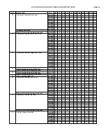
On all units, the pressure switch(es) will interrupt power
to the control module under a blocked flue or inlet
condition. This will cause the pilot and main gas valves
to close. Tables 16 and 17 identify how pressure switch
control changes during boiler/water heater staging.
Tables 18 and 19 identify the control actions if a low air
condition occurs at any stage.
Table 16 - Pressure Switch Control,
L225-L400
Table 17 - Pressure Switch Control,
L600-L2300
Table 18 - Low Air Condition Action,
L225-L2300
Table 19 - Low Air Condition Action,
L600-L2300
OPERATION SEQUENCE, ON/OFF
L225 through L2300
Note: Refer to the wiring diagram included with the
unit for further control system info.
POWER ON:
Demand for Heat:
1. The operator switch closes, energizing pump delay
timer TD4 and the water pump(s).
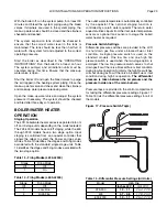
2. Water fl ow through the unit closes the water fl ow
switch contacts energizing blower delay timer TD3.
3. The system checks all primary limit(s) and other
interlocks before starting pre-purge. The unit will not
start if any switch is open.
Stage
Control
Action
1
No Power to Flame Sense Module
Stage
Pressure Switch Mode
Off
Off
1
Low
Fire
2
High
Fire
Stage
Pressure Switch Mode
Off
Off
1
High
Fire
Stage
Control
Action
1
No Power to Flame Sense Module
2
No Power to Flame Sense Module