background image

13 

Raz-AP/SP Dealer Manual 
20170110 


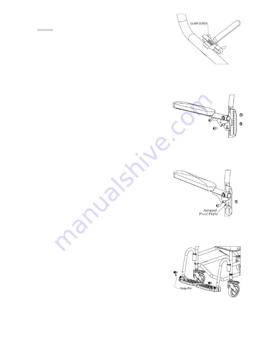
3.5 Wheel Lock Adjustment 

– SP Model


Tool required: (1) 5mm hex key 
1.   Loosen (do not remove) the clamp screws on one wheel lock. 
2.   Shift  the  wheel  lock  along  the  frame  so  that  it  engages  with 

the wheel and stops all wheel movement. 

3.   Tighten the clamp screws. 
4.   Repeat steps 1 to 3 for the other wheel lock.


Note: A properly adjusted wheel lock will prevent the wheel from 
rotating without being too difficult for the user to engage. 


3.6 Armrest Adjustment 

–  Adjusta-Back Option


3.6.1    Armrest Height Adjustment


The  armrests  are  adjustable  in  height within a 

3” range, in ½” 

increments 

on  the  Adjusta-Back  Option 

only


Tools required: (1) 5/16

” hex key, (1) 9/16” wrench 

1.   Loosen and remove the lower locknut. 
2.   Loosen and remove the top locknut. 
3.   Keeping the armrest and armrest pivot plate assembly together, 

move  the  unit  up  or  down  on  the  armrest  support  weldment 
depending on the user

’s needs. 

4.   Replace the locknut onto the top screw. 
5.   Replace the locknut onto the bottom screw. 
6.   Tighten screws and locknuts at the top and bottom. 
7.   Repeat steps 1 to 6 for other armrest. 


3.6.2    Armrest Angle Adjustment


The  armrest  angle  can be  adjusted  up  5°  or  down  5°  if  the 
backrest angle is adjusted from the 90° factory position. 
Tools required: (1) 5/16

” hex key, (1) 9/16” wrench 

1.   Loosen  and  remove  the  screw,  washer  and  locknut  on  the 

bottom of the armrest pivot plate. 

2.   Keeping the upper screw in place, rotate the armrest assembly 

until the preferred position is reached by aligning one of the 3 
holes (arranged in a triangle) on the armrest pivot plate with the 
holes on the armrest support weldment. 

3.   Insert the screw into the preferred position on the armrest 

pivot plate and attach the locknut. 

4.   Tighten the screw and locknut. 
5.   Repeat steps 1 to 4 for the other armrest.


3.7 Adjustable Footrest Adjustment


1.   Remove a plastic snap-pin from one footrest hanger tube. 
2.   Adjust the footplate extension tube vertically to achieve the 

desired height in the footrest hanger tube. 

3.   Insert the snap-pin through the footrest hanger tube and the 

extension tube. Ensure that the snap-pin is completely through 
the  tube  and  that  the  green  plastic  clip  is  snapped 
securely around the outside of the hanger tube. 

4.   Repeat steps 1 to 3 for the other footplate.


Summary of Contents for AP

Page 1: ...Rehab Shower Commode Chairs Raz AP SP Dealer Manual A guide to help authorized Raz dealers safely set up and adjust Raz Rehab Shower Chairs 20170110...

Page 2: ...asters on all models are equipped with dual locks The step on lever activates both the roll lock and the swivel lock It is essential that all casters on the shower chair be in an outward position befo...

Page 3: ...P Shower Chair in any other manner than by an attendant IMPORTANT THE REARWARD STABILITY OF THE RAZ SP IS AFFECTED BY THE MOUNTING LOCATION OF THE REAR WHEELS THE PHYSICAL AND CLINICAL CHARACTERISTICS...

Page 4: ...w the casters rear wheels to grip the floor securely Transfers should never be attempted with the shower chair positioned on slippery surfaces It is recommended that transfers be performed on clean dr...

Page 5: ...nt 10 3 2 Molded Seat Depth Adjustment 11 3 3 Seat To Floor Height Adjustment 11 3 3 1 Seat To Floor Height Adjustment AP Model 11 3 3 2 Seat To Floor Height Adjustment Front Casters of SP Model 11 3...

Page 6: ...8 46cm SEAT DEPTH front of back post to front of seat 16 or 19 40 or 48cm 16 or 19 40 or 48cm 16 or 19 40 or 48cm CLEARANCE HEIGHT with pan brackets without pan brackets 15 5 19 5 39 50cm 16 25 20 25...

Page 7: ...t the backrest up to secure it in place and then place the second coved spacer on the other backrest tube and then lift the backrest to an upright position 4 Insert an 1 3 4 button head cap screw thro...

Page 8: ...r and nyloc nut 5 Tighten the assembly with the hex key and wrench until the end of the screw extends 1 or 2 threads beyond the nylon locknut 6 Repeat steps 3 to 5 for other frame tube TOP VIEW OF BAC...

Page 9: ...R BE ADJUSTED TO DIFFERENT HEIGHTS AN UNLEVEL CHAIR IS EXTREMELY DANGEROUS FOR ANY USER CASTERS SHOULD ALWAYS BE INSTALLED AT THE LOWEST POSITION POSSIBLE WHILE MEETING THE USER S NEEDS ANY POSITION A...

Page 10: ...ATTEMPTED WITH THE USER IN THE CHAIR 3 1 Backrest Adjustment 3 1 1 Backrest Angle Adjustment Tools required 1 3 16 hex key 1 7 16 wrench 1 Loosen and remove the locknuts washers and coved spacers SP m...

Page 11: ...ster extension tube in place from the chair frame 2 Slide the caster assembly to the desired position 3 Align the holes in the caster extension tube with the frame holes and insert the snap pins TIP L...

Page 12: ...3 4 wrench 2 7 16 wrenches 1 Loosen the wheel locks 2 Remove the hubcap of one wheel by twisting it counter clockwise Loosen and remove the axle bolt and locknut and set aside the wheel assembly TIP...

Page 13: ...s at the top and bottom 7 Repeat steps 1 to 6 for other armrest 3 6 2 Armrest Angle Adjustment The armrest angle can be adjusted up 5 or down 5 if the backrest angle is adjusted from the 90 factory po...

Page 14: ...e wound through each component as they are removed 2 Remove the back upholstery from the back frame and machine wash with a mild detergent in warm water on a normal or gentle wash cycle Include other...

Page 15: ...ENSURE THAT ANY SOAP OR DETERGENT RESIDUE IS REMOVED DO NOT USE CLEANING PRODUCTS WITHOUT CONSULTING THE PRODUCT S INSTRUCTIONS AND TAKING APPROPRIATE PRECAUTIONS FOR HUMAN EXPOSURE TO CHEMICALS 6 0 C...

Reviews: