RayTek MARATHON FA, Operating Instructions Manual
The RayTek MARATHON FA comes with a comprehensive operating instructions manual, providing users with detailed guidance for optimal usage. This manual is available for free download from our website, ensuring easy access and convenience. Unlock the full potential of your MARATHON FA by referring to the downloadable manual on manualshive.com.
Share
Download


Reviews:
No comments
Related manuals for MARATHON FA
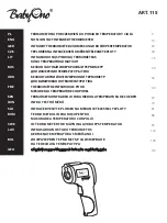
115
Brand: BabyOno Pages: 124

25311
Brand: hager Pages: 5

THERMO-FIXX 0123 Series
Brand: KWB Pages: 24

1F87-0261
Brand: White Rodgers Pages: 12

CT111C
Brand: IROX Pages: 5

HH203A
Brand: Omega Engineering Pages: 26

HQWT-T-HW
Brand: Homeworks Pages: 12

15-930-000
Brand: HealthSmart Pages: 2

RT300RF
Brand: Salus Pages: 24

T2900SCH
Brand: Venstar Pages: 1

ST320RF
Brand: Salus Pages: 32

86 73 97
Brand: Westfalia Pages: 16

RCD3
Brand: Seltron Pages: 34

LT800
Brand: GTC Pages: 2

3204
Brand: Summer Pages: 25

03006
Brand: Summer Pages: 56

Pro Digital Remote
Brand: prowarm Pages: 2

8840
Brand: Aprilaire Pages: 44


