61
VERSA
MASTER
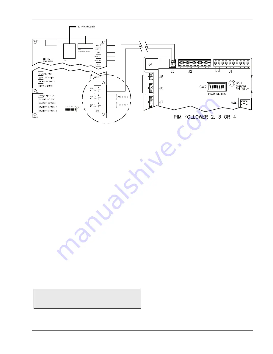
Fig. 42: Cascade System Wiring
Cascade System Pump and Sensor
Wiring
1. On the boiler designated as the Master, connect
the system pump wiring to the System pump out-
put terminals. The output is rated for pilot duty only
(2A maximum). For System pump operation during
limp-along mode, it is recommended to connect
the system pump outputs from each unit in paral-
lel.
2. Connect the boiler pump wires to the boiler pump
terminals or associated relay, based on model
type and size.
3. Connect the system supply sensor to the MAS-
TER, per the instructions provided with the unit.
4. Connect the Outdoor Sensor (if used) to the MAS-
TER, per the instructions provided with the unit.
the Master PIM™.
5. Connect the Enable/Disable wiring to the Master.
This connection must be provided through dry
contacts closure. For each follower to be opera-
tional during limp-along mode the enable must be
jumpered at each unit.
Cascade Follower Pump and Sensor
Wiring
1. Once the Master has been identified, additional
boilers will be designated as Followers. DIP switch
#2 on each follower VERSA
®
board must be set to
the OFF/Down position.
2. For each follower boiler, connect the boiler pump
wires to the terminal block at the rear of each unit.
Connect to terminals 4, 5, and 6.
3. The System pump and DHW pump outputs may
be configured for use during limp-along mode.
See page 53 - 54.
Alarm Connection
An alarm bell or light may be connected to the alarm
contacts on the boiler PIM™. The Alarm Contacts are
3A rated dry contacts on a normally-open relay that
closes during fault or lockout conditions, and the max-
imum voltage across the contacts is 30 VAC or
30 VDC.
Connections are made at J1 pins 1 and 2 on the boil-
er PIM™. In a cascade system, the alarm output of all
connected units will be active if either the master boil-
er or follower(s) have a lockout condition.
NOTE:
This dry contacts closure can come from a
room thermostat or a remote relay. No power of any
kind should be applied to either of these terminals.
Summary of Contents for VERSA IC
Page 2: ...2 Rev 2 is a software revision J1214G Aug 2014 completely new edition of this manual...
Page 78: ...78...
Page 79: ...79...


